@jim-p On my schematic I have put in Lm393. Still not working correctly so am looking at what I'm doing wrong
Post your last version and we take a look.
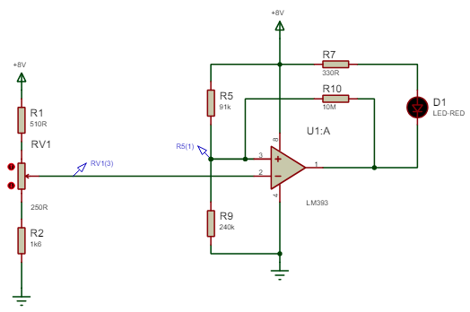
comparator circuit LM393.PDF (9.8 KB)
I have got this circuit to turn the LED on and off as I want it to.
How would I get it to work with 2 comparators for 2 inputs
Uploading your schematic as an image is a lot more convenient than PDF.
Replicate the same circuit with appropriately chosen resistors.
I'm surprised that you end up needing 10Meg for R10. Sounds kind of high; I'd scale down everything by an order of magnitude or so (except R7).
That was the only value that would work. Anything lower and it didn't work
The circuit in #9 (and #10) makes an adjustable deadband gap by essentially connecting one end of a pot to your R5(1) node, the other end to ground (or a node partially towards ground), and the wiper of the new pot to the second comparator reference. This makes a reference voltage lower than the one created by R5&R9.
comparator circuit LM393.PDF (10.7 KB)
Does this look correct. It is working as I want on the simulator
You are very close to the absolute maximum sinking current rating. I would reduce it to 10mA or less. So change R7 and R8 to 680 ohms
Oherwise, if it does what you want, it must be correct.
LM393 with relays.PDF (11.8 KB)
I've removed the LED's and added the relays
Does it worK?
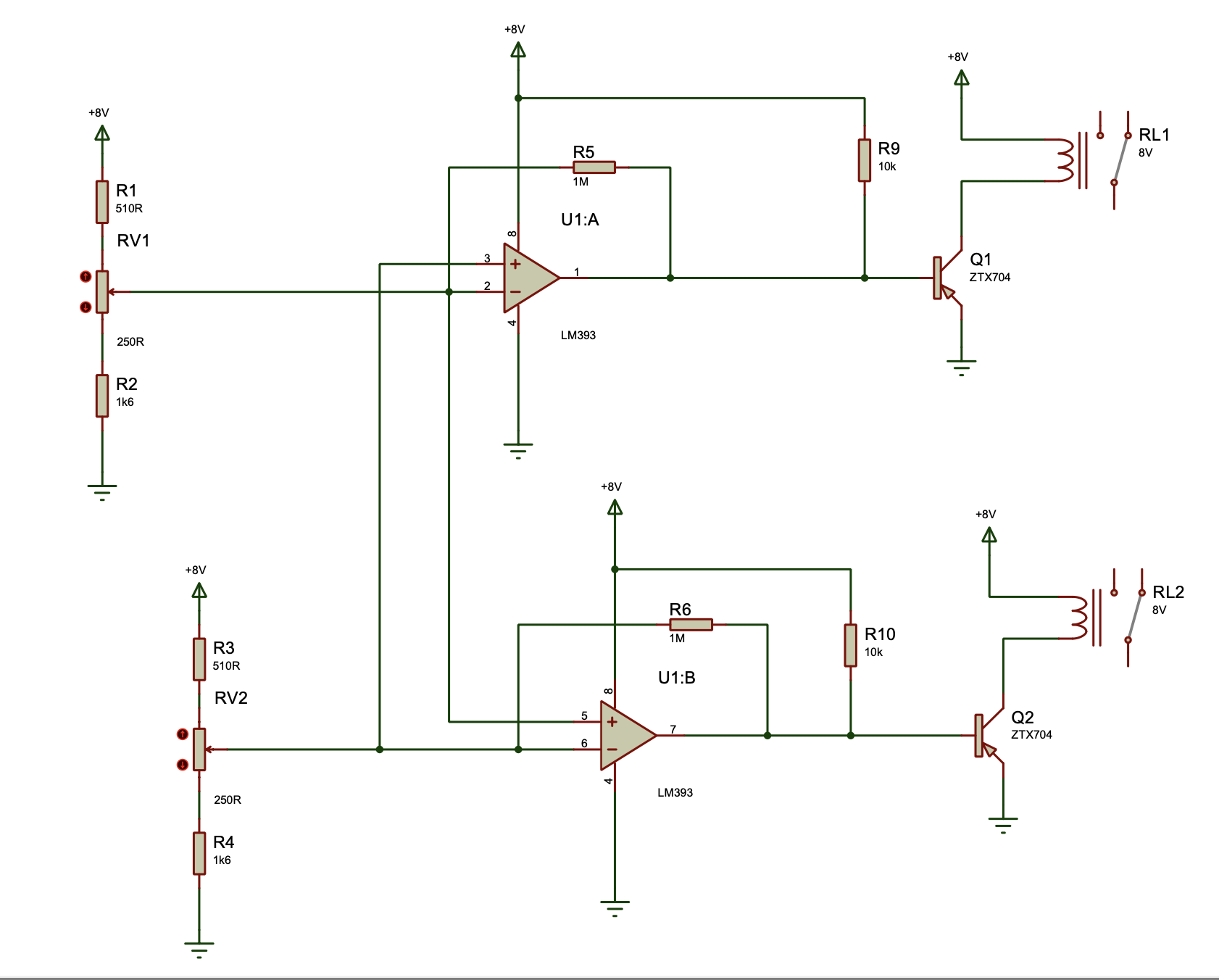

If I us NPN then the relays are energised when both inputs to the LM393 are equal to each other
If it is pnp, the load should run from collector to gnd and the emitter should be at vcc...
Are you sure you have it upside down like in your schematic?
And for the hysteresis, the feedback resistors should go to the non inverting (positive) input of the comparators.
You can not use PNP transistors in that circuit. With the emitter grounded, you need a negative voltage on the base to turn it on and there is no negative voltage available.
Does it work?
@jim-p It does on the simulator. Going to try it properly to see if it works
Ok.
Can you show us the circuit?
The circuit is in post 13