Different circuit schematics to refer to:
- DIY basic Logic Probe and Logic Plulser.
- @ 5V, Logic Probe's load is ~1.6mA.


- let’s say we have circuit S4.
Let’s say the switch is 10 feet from the Arduino.
This means we are taking the +5v supply line out 10 feet and 10 feet back.
5v is now extended 20 feet with the potential of it coming in contact with things that can go pop if there was ever a short circuit on the cable.
Also, sending 5v out on a 20 foot wire allows inductive coupling to noise sources that can cause serious problems back at the Arduino. - If we are using S5, the R8 pull-up is back at the Arduino, the switch is 10 feet away as before.
If there was a short on the 10 feet of wire, the external pull-up (R8) limits the short circuit current.


Example:


Protect GPIOs

Protect GPIOs from our blunders


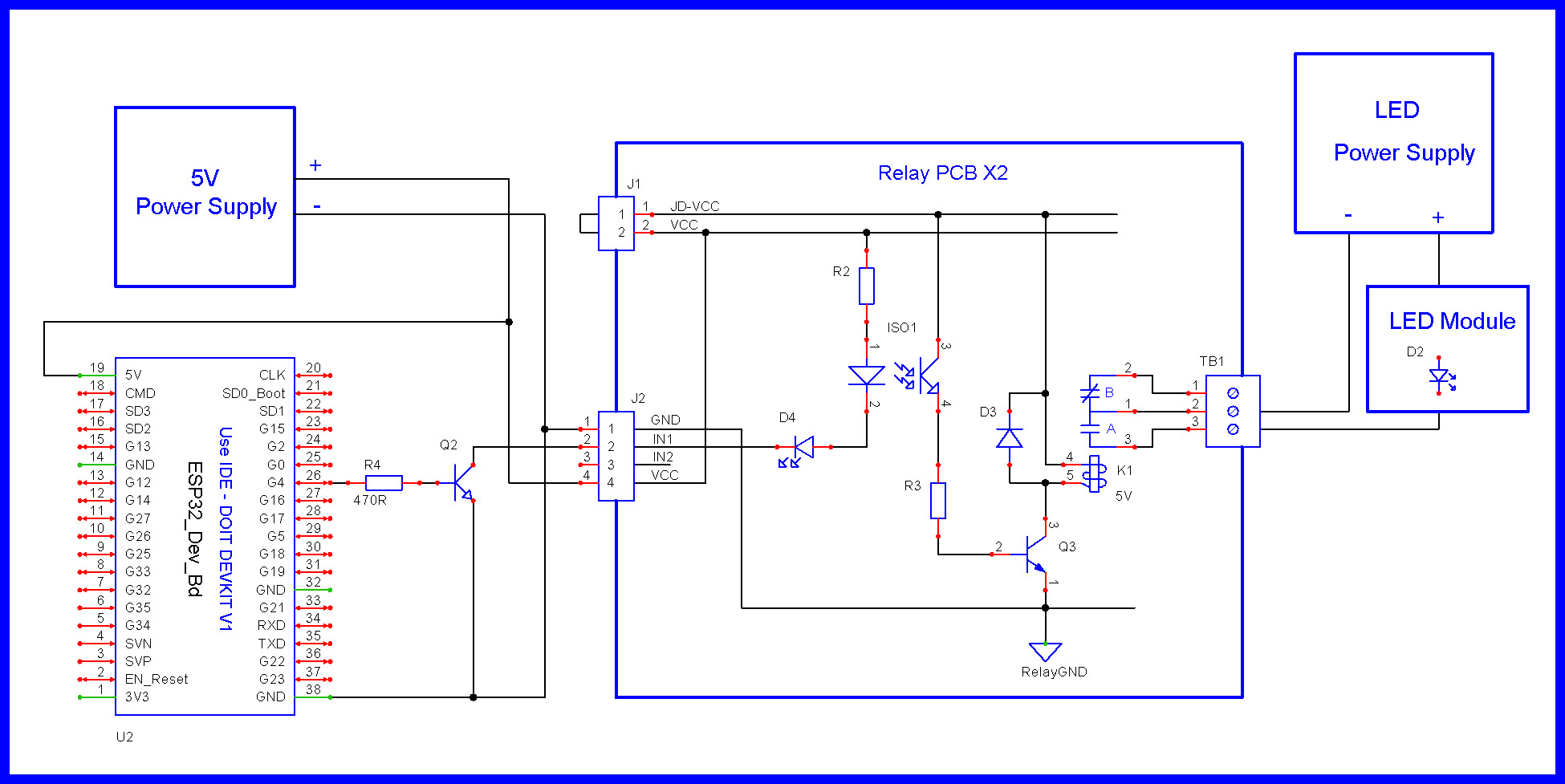
LED Example Circuits


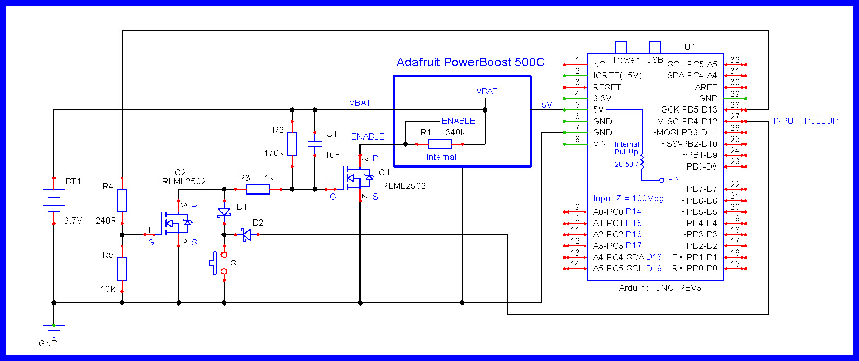
Power ON with switch, program controlled power OFF
- Yellow is installed if you want the switch/sensor (going to 5V) to turn on power.
- Green is installed if you want the switch/sensor (going to GND) to turn on power.

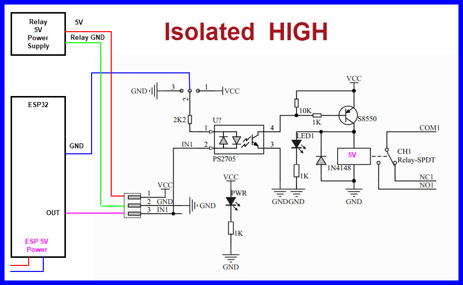
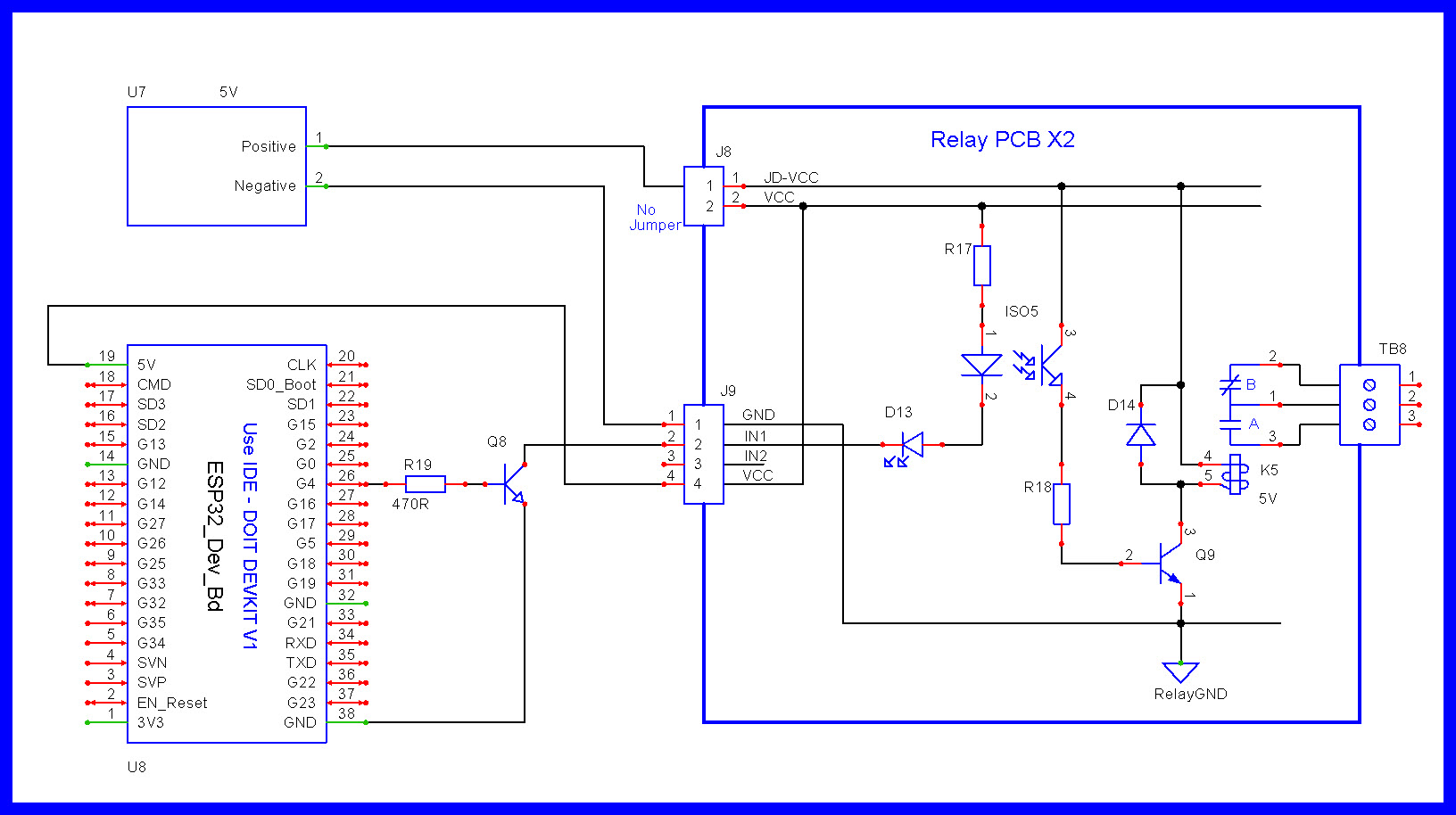
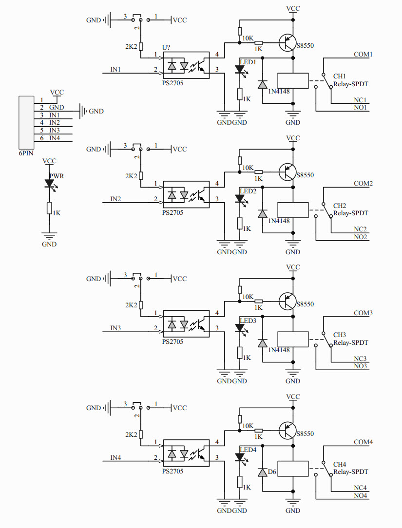
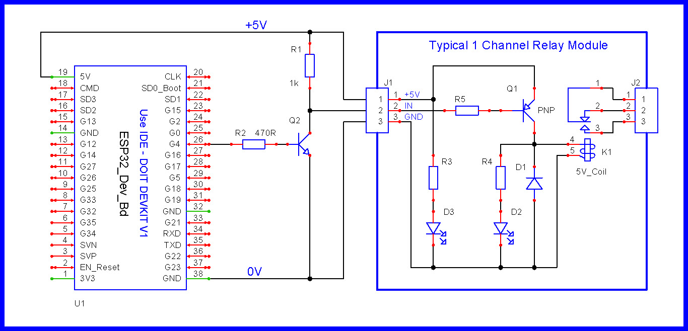
Universal relay board.

OR


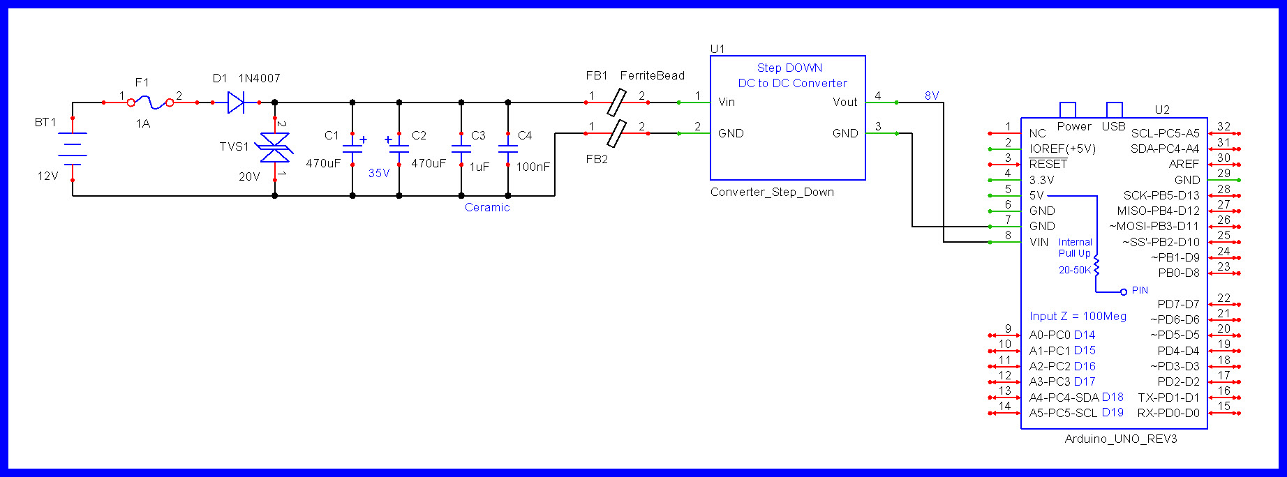
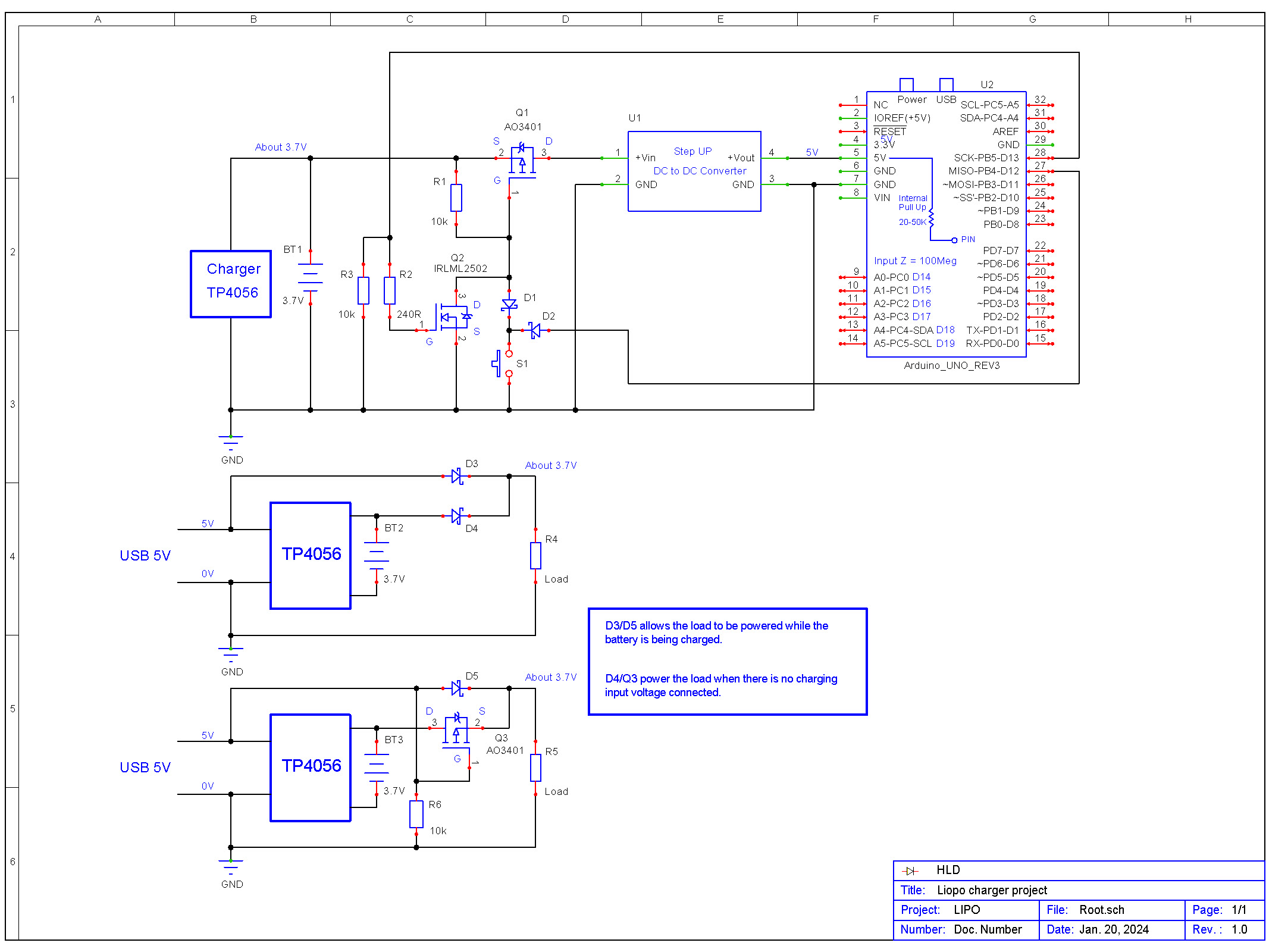
Reverse Polarity Protection and High Side Switch

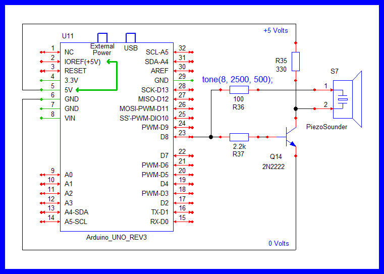
Piezo Speaker
Power Control


2 Channel commercial relay module:

8 channel relay board, @ddloydddloyd

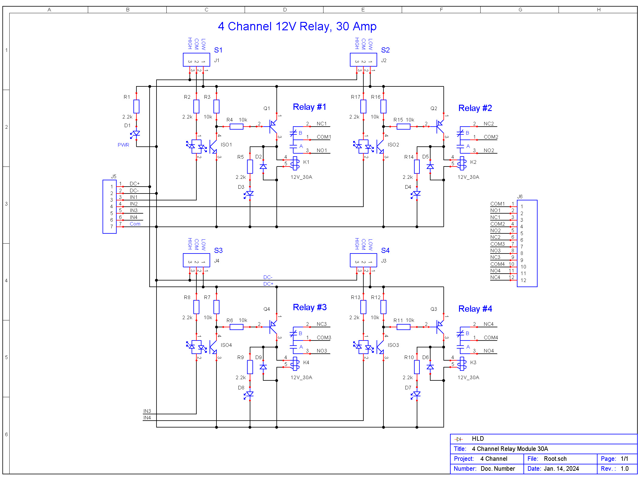
4 channel

4 channel relay board
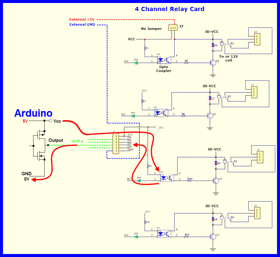
HIGH/LOW input option, relay cards