Hi, I have an arduino UNO and a sensor. The sensor operates in 3.3 V logic and the arduino on 5v logic. I use a level converter. The sensor has a passive response, when it is sent a 9 byte string over uart it responds with a 13 byte string containing oxygen level, temperature level, and humidity level.
When I connect the arduino using the diagram below and run the script, nothing is outputted to the serial monitor. I tried running the output from the logic converter to an analog port on the arduino and the signal shows 3.3 volt constant. This seems like the signal is not being sent, but I’m not sure if it because of the way I am testing it. I plan to test the same method tommorow using an oscilloscope instead of the analog port but thought I would ask for advice in the meantime. I have attached the datasheet of the sensor, an image of the setup, and the arduino script. Please note the setup is not the same as the diagram because I took the picture after trying to trouble shoot. My main thought is if the way I’m trying to send the serial data request signal correct? Please let me know if any more data is needed. Sensor datasheet thanks for any and all help.
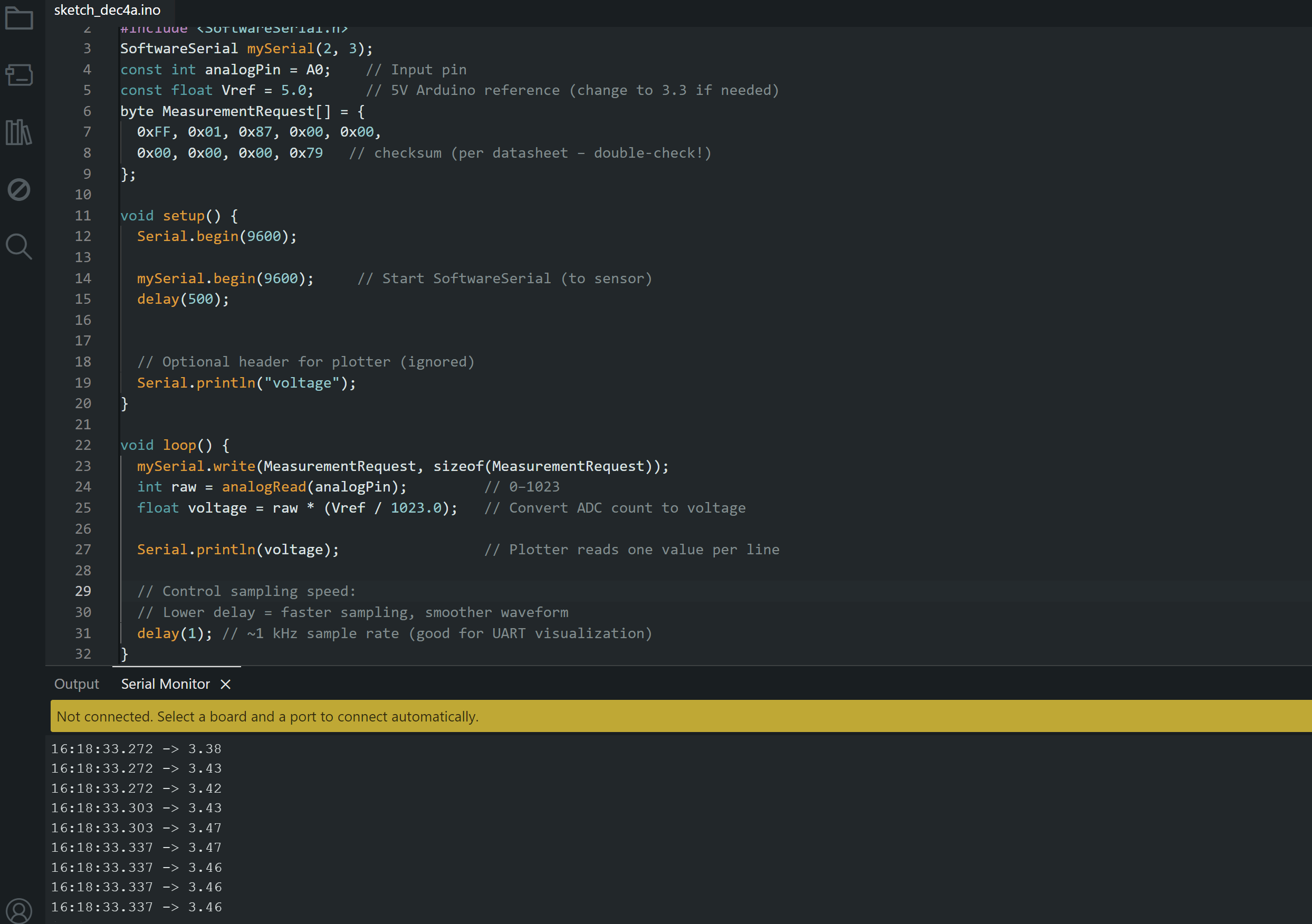
This is the script I used to check if the signal is present at all, I modified my original script and didn’t save it but I was reading 13 bytes according to the manual. There is a manual for the sensor+ PCB in the original post, can you not open this?
Sorry about the code I don’t have access to my computer until tommorow, I meant to post it to see if my overall idea was right or if there were any glaring issues. For the first code i sent, I had connected the TX output of the sensor directly to the A0 header on the arduino to try and troubleshoot. This is what resulted in the output of 3.3V over and over.
@chogikyan
If you wish you can get rid of the active level shifter by the following passive level shifter only for RX line to simplify the wiring. Do you own the physical sensor? If yes, post the picture.
On the reading side the function readBytes() can timeout so you should trap that as it returns the number of bytes placed in the buffer. A value of 0 indicates that no valid data was found. Best is to just check if you did actually read the expected number of bytes.
Typically we wait for data to start arriving and then read hoping the frame will be there without problem
while (SUART.available() == 0) yield(): // block waiting for answer
// something started to arrive, read the payload
if (SUART.readBytes(myData, 13) == 13)  {
  // We got 13 bytes. Handle the payload
  …
} else {
  // handle error
  …
}
But this is not the ideal way as it’s blocking. This is an asynchronous protocol so best read with an asynchronous code. Just read data in a buffer as it comes back in and handle the rest of your code (monitoring buttons or whatever) until you got the payload - then deal with the payload .
Also please, please never ever again post pictures of text... Not only they are not readable nor usable directly for copy&paste but they use up lots of storage and internet bandwidth which contributes to polluting the planet.
➜ do your part and do yourself a favour and please read How to get the best out of this forum and modify your post accordingly (including code tags and necessary documentation for your ask).
void loop()
{
  byte y = SUART.read();
  if (y != 0)   //checking that 1-byte data has arrived in Serial buffeer
  {
    byte m = SUART.readBytes(myData, 9);  //reading all the 9-byte of the frame
    if (m == 9)   //9-byte data hasve arrived
    {
      if (myData[0] == 0xFF && myData[1] == 0x86)  //validatae Header AND ID
      {
        //------------------------------
      }
    }
  }
}
read returns -1 as an int (so != 0) when there is nothing to read. even if you store that into into a byte you won't get 0, you'll get 0xFF when there was nothing to read and you don't know then if you actually did receive 255 as a byte or if it was an error.
I should have written SUART.available() in place of SUART.read().
void loop()
{
  byte y = SUART.available();
  if (y != 0)   //at least there is 1-byte data in Serial buffeer
  {
    byte m = SUART.readBytes(myData, 9);  //reading all the 9-byte of the frame
    if (m == 9)   //9-byte data hasve arrived
    {
      if (myData[0] == 0xFF && myData[1] == 0x86)  //validatae Header AND ID
      {
        //------------------------------
      }
    }
  }
}
Asynchronous/nonblocking version:
void loop()
{
  byte y = SUART.available();
  if (y != 0)   //at least there is 1-byte data in Serial buffeer
  {
    myData[i] = SUART.read();
    i++;
    if(i == 9)
    {
      if (myData[0] == 0xFF && myData[1] == 0x86)  //validatae Header AND ID
     {
        //------------------------------
        i = 0;
     }
    }
  }
}
I am going back to the lab now i will post a picture of the sensor. My plan of attack is to set up the original schematic but replace the logic converter with a voltage divider per @GolamMostafa ‘s advice. If that does not work with the original code (from post 14) i will try implementing the code sent by @J-M-L because to me it seems like my code should have worked anyway, so it must be a problem with the setup.
Any advice on how I should troubleshoot if the voltage divider setup doesn’t work would be greatly appreciated. My first thought would to be measuring each digital signal with an oscilloscope and trying to work backwards from sensor output to sensor input to arduino output to see which signal is flat (always a 1).
1. The passive level shifter using voltage divider had worked well for me in UNOR3/ESP32 UART operation.
2. Try the following sketch to acquire Gas concentration, Temperatue, and Humidity in passive mode. The Serial Monitor shows only Temperature and Humidity.
#include<SoftwareSerial.h>
SoftwareSerial SUART(5, 6);
byte myData[13];

void setup()
{
  Serial.begin(9600);
  SUART.begin(9600);

  //-------passive mode---------
  uint8_t autoCmd[9] = {0xFF, 0x01, 0x78, 0x40, 0x00, 0x00, 0x00, 0x00, 0x46};
  for (byte i = 0; i < 9; i++)
  {
    SUART.write(autoCmd[i]);
  }
}

void loop()
{
  //---- read command--------
  uint8_t gthReadCmd[9] = {0xFF, 0x00, 0x87, 0x40, 0x00, 0x00, 0x00, 0x00, 0x79};
  for (byte i = 0; i < 9; i++)
  {
    SUART.write(gthReadCmd[i]);
  }

  //----read gas, temp, humidity data-------------
  byte y = SUART.available();
  if (y != 0)
  {
    byte m = SUART.readBytes(myData, 13);
    if (m == 13)   //13-byte data hasve arrived
    {
      if (myData[0] == 0xFF && myData[1] == 0x87)  //Frame Header AND Command ID
      {
        int rawTemp = (myData[8] << 8) | myData[9];
        int rawHum  = (myData[10] << 8) | myData[11];

        float temp = rawTemp / 10.0;
        float hum  = rawHum / 10.0;

        Serial.print("Temperature: ");
        Serial.print(temp, 1);
        Serial.println(" °C");

        Serial.print("Humidity: ");
        Serial.print(hum, 1);
        Serial.println(" %RH");

        Serial.println("------------------------");
        delay(1000);
      }
    }
  }
}
Hi I think I’m messing up something really stupid. When no ground or 5 volt lines connected, I messed the correct resistance values. When I plug arduino in (unpowered) I get a resistance of 1.5 kohm over the first resistor as if there is a resistor in parallel. I thought maybe there is some connection between the arduino (ground and 5v) when powered off.i tried with power on and measure only 1.6 V on the right power line where I should have 3.3. What am I doing wrong?
Never mind I turned it off and on and the voltage divider works now . I will try sending the signal over this divider instead of the prebuilt logic converter