Hi, Can you help me with this?
I want to understand why this is not working
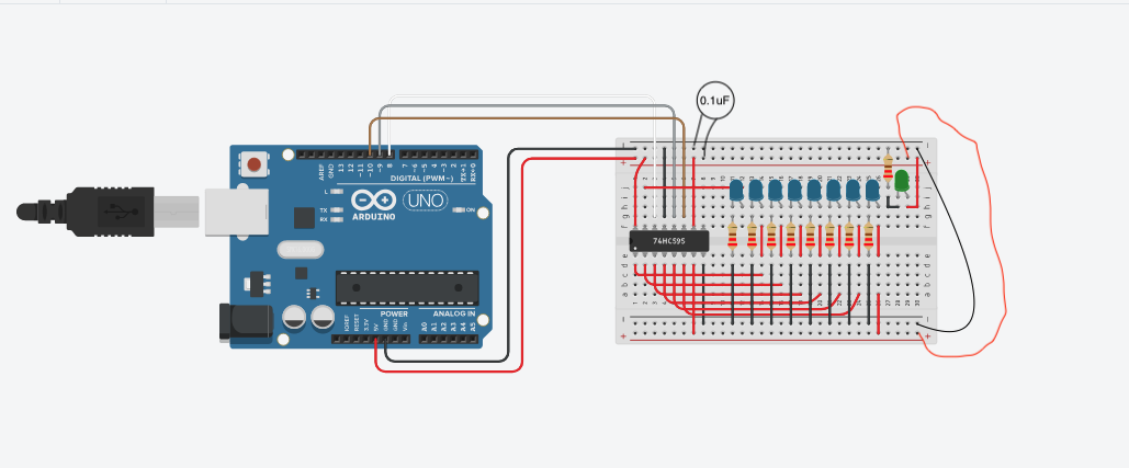
Links:
Arduino Image Link:
Site where the project is created:
Project Link:
Code:
// Abre/Fecha o componenete para inserir um byte
int Clock = 10; // Clock > SHCP
int Leth = 9; // Leth > STCP
int Dados = 8; // Dados > DS

void setup(){
	pinMode(Clock, OUTPUT);
  	pinMode(Leth, OUTPUT);
  	pinMode(Dados, OUTPUT);
  	pinMode(12, OUTPUT);
  digitalWrite(12, HIGH);
  	Serial.begin(9600);

}


void loop(){
  delay(500);
	registerSet();
  delay(500);
  //delay(1500);
 	//registerSet2();

}


void registerSet(){
  byte ledMode = 1;
  digitalWrite(Leth, LOW);
  for(int i=0; i<9; i++){
    Serial.println(ledMode);
  	digitalWrite(Clock, LOW);
    digitalWrite(Dados, ledMode);
    if(ledMode == 1){ledMode = 0;}else{ledMode = 1;}
    digitalWrite(Clock, HIGH);
  }
  digitalWrite(Leth, HIGH);
}
/*
void registerSet2(){
  digitalWrite(STCP, 0);
  for(byte i=0; i<=7; i++){
  	digitalWrite(SHCP, 0);
    digitalWrite(DS, 0);
    digitalWrite(SHCP, 1);
  }
  digitalWrite(STCP, 1);
}
*/
English by: Google translator
Code.ino (920 Bytes)