Hello Guys I am having some problems, so I bought the elegoo car v.40 car kit and I am having trouble coding it. its purpose is if it hears any weird noises it brings the perscibed medication to the user. The thing is my team is running into some difficulties because it use to work a couple days ago but now it is not even moving when we are using the remote I asked AI but even they could not help my teammate says that it is not working due to the fact that the little RGB light In front of the uploading port is not lighting up is he correct or is it another reason and how can we fix it
How does it determine "weird"... or medication... or user?
I doubt this.
AI is not a "they" it gathers statistics of the words you use. It "knows" nothing.
Your teammate does not understand, and is guessing, just as badly as AI.
Before your project moves, your project must have the correct power. I assume you have some power supply made of batteries. Make certain the power supply is the correct size and has enough power.
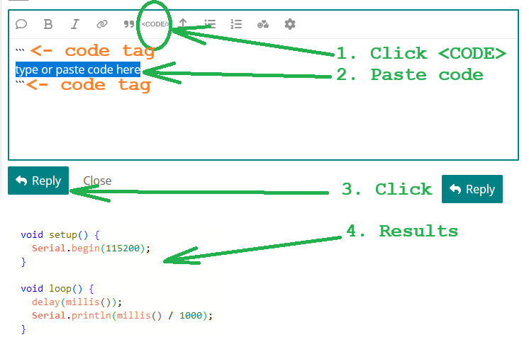
While you are measuring your power supply, show the wiring diagram of all the devices you are using in your project. Also, post the sketch you are using. in a Code Block:

1 Like
This is very similar to the V3 we made quite some time ago with my daughter. The power supply is a rechargeable pack about the size of a 4 x AA battery holder but I have no idea what the battery chemistry is. There is a little switch on the side to turn power on and off. It has a motor controller board, an Elegoo UNO R3 on top with a shield plugged in. The shield has QWIIC connectors for all the peripheral cables. Into this is also plugged in a HC05 Bluetooth board. The remote is IR and the shield has an IR sensor on top, although its positioned somewhat awkwardly next to and almost under the Bluetooth board so you have to aim at just the right angle to get it to receive. Its actually a bit easier top operate the car without that Bluetooth board being plugged in. The front of the car has an HC-SRO4 type ultrasound sensor.
From online photos of the V4, Elegoo appear to have added an ESP32 CAM to the front of the car and modified the shield to accommodate an additional QWIIC connector so that it can be connected to the rest of the kit. The board shown in the Elegoo photo that I saw does not include an onboard microphone. Maybe OP has an updated version?
I expect that for OPs kit, there will be two sketches, one for the Elegoo UNO R3 and one for the ESP CAM.
I do certainly think it would be useful to have details of any modifications (hardware or software) that may have been made to the original Elegoo kit. However, also check the obvious first, such as maybe it being left on over night and the battery is drained. Its easily done.
Yes. I got a (Lafvin) 2WD kit to see if I could duplicate issues on this forum, after "missing instructions" mostly pointed to the battery (charge) followed by bluetooth connection (password, wiring). LAFVIN 2WD Smart Robot Car Kit V2.2 (updating)
1 Like
Thank you for all your help I just need one more thing do any of you know the original code or how to reset my Elegoo uno r3 to the original code
Elegoo does.
So is the program that it came with
Only you know what the kit did when you first got the kit. There are many "demo" programs in the link, most are for setup, all are modular. Decide which modules work best.
In addition to the Elegoo v4 link, here is Elegoo's GitHub page for the V4 software.
Hello again and thank you for all the help but if you dont mind how would this code be
"/* =========================================================
FILE: SmartRobotCarV4.0_V1_20230201.ino
========================================================= */
#include <avr/wdt.h>
#include "ApplicationFunctionSet_xxx0.h"
void setup() {
Application_FunctionSet.ApplicationFunctionSet_Init();
}
void loop() {
Application_FunctionSet.ApplicationFunctionSet_SerialPortDataAnalysis();
}
/* =========================================================
FILE: ApplicationFunctionSet_xxx0.h
========================================================= */
#ifndef APPLICATION_FUNCTION_SET_XXX0_H
#define APPLICATION_FUNCTION_SET_XXX0_H
#include <Arduino.h>
class ApplicationFunctionSet {
public:
void ApplicationFunctionSet_Init(void);
void ApplicationFunctionSet_SerialPortDataAnalysis(void);
};
extern ApplicationFunctionSet Application_FunctionSet;
#endif
/* =========================================================
FILE: ApplicationFunctionSet_xxx0.cpp
========================================================= */
#include "ApplicationFunctionSet_xxx0.h"
#include "DeviceDriverSet_xxx0.h"
#include "IRremote.h"
ApplicationFunctionSet Application_FunctionSet;
void ApplicationFunctionSet::ApplicationFunctionSet_Init(void) {
AppMotor.DeviceDriverSet_Motor_Init();
AppIR.DeviceDriverSet_IR_Init();
}
void ApplicationFunctionSet::ApplicationFunctionSet_SerialPortDataAnalysis(void) {
AppIR.DeviceDriverSet_IR_Deal();
}
/* =========================================================
FILE: DeviceDriverSet_xxx0.h
========================================================= */
#ifndef DEVICE_DRIVER_SET_XXX0_H
#define DEVICE_DRIVER_SET_XXX0_H
#include <Arduino.h>
class DeviceDriverSet_Motor {
public:
void DeviceDriverSet_Motor_Init(void);
void DeviceDriverSet_Motor_control(boolean direction_A, uint8_t speed_A,
boolean direction_B, uint8_t speed_B,
boolean controlED);
};
class DeviceDriverSet_IR {
public:
void DeviceDriverSet_IR_Init(void);
void DeviceDriverSet_IR_Deal(void);
};
extern DeviceDriverSet_Motor AppMotor;
extern DeviceDriverSet_IR AppIR;
#endif
/* =========================================================
FILE: DeviceDriverSet_xxx0.cpp
========================================================= */
#include "DeviceDriverSet_xxx0.h"
#include "IRremote.h"
#define IR_RECEIVE_PIN 2
IRrecv irrecv(IR_RECEIVE_PIN);
decode_results results;
DeviceDriverSet_Motor AppMotor;
DeviceDriverSet_IR AppIR;
void DeviceDriverSet_Motor::DeviceDriverSet_Motor_Init(void) {
pinMode(4, OUTPUT);
pinMode(5, OUTPUT);
pinMode(7, OUTPUT);
pinMode(8, OUTPUT);
pinMode(3, OUTPUT);
pinMode(6, OUTPUT);
pinMode(9, OUTPUT);
digitalWrite(9, HIGH);
}
void DeviceDriverSet_Motor::DeviceDriverSet_Motor_control(boolean direction_A, uint8_t speed_A,
boolean direction_B, uint8_t speed_B,
boolean controlED) {
digitalWrite(4, direction_A);
digitalWrite(5, !direction_A);
digitalWrite(7, direction_B);
digitalWrite(8, !direction_B);
analogWrite(3, speed_A);
analogWrite(6, speed_B);
}
void DeviceDriverSet_IR::DeviceDriverSet_IR_Init(void) {
irrecv.enableIRIn();
}
void DeviceDriverSet_IR::DeviceDriverSet_IR_Deal(void) {
if (irrecv.decode(&results)) {
switch (results.value) {
case 0xFF629D: // Forward
AppMotor.DeviceDriverSet_Motor_control(true, 150, true, 150, true);
break;
case 0xFFA857: // Backward
AppMotor.DeviceDriverSet_Motor_control(false, 150, false, 150, true);
break;
case 0xFF22DD: // Left
AppMotor.DeviceDriverSet_Motor_control(false, 150, true, 150, true);
break;
case 0xFFC23D: // Right
AppMotor.DeviceDriverSet_Motor_control(true, 150, false, 150, true);
break;
case 0xFF02FD: // Stop
AppMotor.DeviceDriverSet_Motor_control(true, 0, true, 0, true);
break;
}
irrecv.resume();
}
}
"
if there are any issues feel free to say i need all the help i can get but in a certain time so by tommorow i need to get my arduino to work so the original stuff it did was move around using the remote and when we clicked one of the numbers it would go around and scan the area