For a project on which I am working on, I need 5 vibration motors that can vibrate independently with various degrees of force.
The problem is that on different sites I see that they use different parts for the wiring (e.g. transistors, resistors and/or capacitors) and thanks to my limited knowledge, I get more confused.
I have tried my best to create a well-working wiring, but I would really appreciate your help in checking my work.
Full Project Wiring-
Vibration Motors Focused Wiring-
Transistor+Diode Focused Wiring-
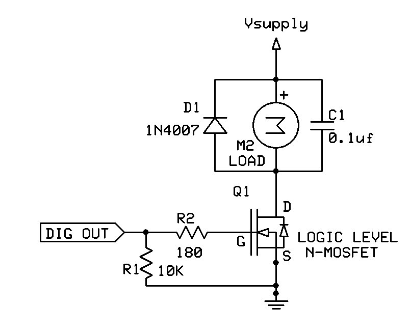
Remade wiring (only 2 motors for ease of reading)
-My project consists of 5 distance sensors (HC SR04), which should give an output to the 5 vibration motors(1027 Vibration Motor 5V, 3W, 0.75A) (the fist sensor controls the first motor, the second sensor controls the second motor and so on...).
Furthermore I have implemented a GPS module (NEO 6M) and a 8 ohm 36mm speaker.
As for the battery, I haven't implemented it yet into the wiring, but I am thinking of using a Portable Power Banks for phones.-
It's almost impossible to tell anything useful from those awful Fritzy things.
E.g. you seem to have the motors connected to the Arduino 5V pin. That's a definite no-no. The Arduino cannot provide anywhere near enough current to run 5 motors (or even one motor).
Your "Capacitor+Diode Focused Wiring" picture doesn't seem to have any capacitors or diodes anywhere in it. That's very confusing. I can see what look like transistors of unknown type and what looks like a resistor.
Please post a conventional circuit diagram with all component values and pin numbers shown. Hand drawn and photographed would be fine, certainly much better than Fritzings.
Steve
slipstick:
It's almost impossible to tell anything useful from those awful Fritzy things.
E.g. you seem to have the motors connected to the Arduino 5V pin. That's a definite no-no. The Arduino cannot provide anywhere near enough current to run 5 motors (or even one motor).
Your "Capacitor+Diode Focused Wiring" picture doesn't seem to have any capacitors or diodes anywhere in it. That's very confusing. I can see what look like transistors of unknown type and what looks like a resistor.
Please post a conventional circuit diagram with all component values and pin numbers shown. Hand drawn and photographed would be fine, certainly much better than Fritzings.
Steve
Oh, sorry for that mistake. I wanted to say Transistor but I wrote Capacitor by mistake.
That resistor looking part is supposed to be a diode.
I am going to retry the wiring so it is more readable tomorrow .
Thank you for your help.
I am going to retry the wiring so it is more readable tomorrow
Please draw it by hand, and post a photo. Don't waste your time and ours with Fritzing.
Here is how you can control a motor from Arduino: