Hi all I recently bought a 20*4 high contrast lcd (High Contrast 20x4 Character LCD - White on Black 5V sorry that is in Greek). I have connected to it an i2c module which I have tested with another screen and works fine. However after connectig the module to the arduino (mega) to the correct pins vcc to 5v gnd to gnd sda to pin 20 and scl to pin 21. The arduino when it gets power it starts like normal and after a few seconds turns of like the poly fuse has pin trip. Is it possible that I am "overcurenting" the arduino? If pictures are need pls tell me.
We need to know how you have wired up everything.
- How is the lcd attached to the i2c module
- how is the i2c module wired to the Arduino
- how is the Arduino powered.
photos can be helpful.
And what s/w are you running on the Arduino?
--- bill
I am on the road so I will send picture in like 30 minutes. The arduino mega is powered via usb at the moment (test run) but it will be powered (the whole project) by ly ion batteries. The i2c board is basically directly connected to the lcd pin for pin. I say basically because I am using wires to go from lcd pin to the i2c instead of using header pins (the stack doesn't fit). I think I have already said how the i2c is connected to the arduino but, just to be sure. The vcc pin of the i2c module is connected to 5v the gnd to gnd sda to pin 20 and scl to pin 21.
About the firmware it is custom made but it was working on the same module with it connected (the same way to a 16*4) lcd. But to be honest I don't think it is a firmware issue since as soon as the screen "turns on" the arduino is like being shorted (it is not a short circuit) and disconnects from the pc.
please
- link to the datasheet of that Display (can't read Greek). We have to check the pin mapping of the connector on the display.
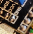
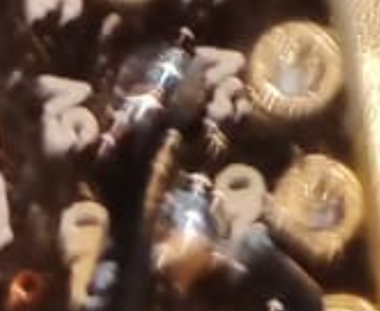
- make clear pictures showing how you have connected the I2C adapter with your display and your MEGA
OK I know the pictures are not ideal (you probably can't see anything) but I meticulously check every wire and they are in order


Also the sda scl gnd and vcc are connected correctly (I don't see the point of sending pictures where you can't see almost nothing)
Γεια σας ioakeimsogiakas
Check the solder joints for short circuits, especially at the power supply lines.

Will do also here is the datasheet-pdf I found
RC2004A-BIW-CSX.pdf (2,6 MB)
I have check my solder joints but I don't see anything obvious. Also my poly fuse is definitely the one being triped. It is getting hot and then it shuts the mega down.
Could it be that the screen is just pulling too much current to work?
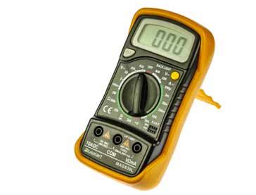
Check it by using a DMM.
Sorry what is dmm?
Lol OK I will
I though it was called a multimeter ![]()
Carry out a measurement of the supply voltage here.
If no 5V is measured, then there is a short circuit on the board.
Then check all solder connections again.
You are right I suppose, The voltage when the arduino turns on rapidly starts to drop till like 0.5 volts. But I can't figure out where the short is. I probed every place on the screen and the i2c. It doesn't have a short
I am thinking on removing the wires tomorrow and solder on some headers to test without i2c
Check that the black wire is going to where the black wire should go, and the other black wire is not going to where the other black wire should.
OK so I unsoldered everything and I have left the back light of is there anything weird with high contrast lcd displays?
