First, I wonder if that setup is compatible with LED flickering. Since to stop the overcurrent, it will create a switching back and forth of Q1. So it will stack up a flickering on my flickering... What do you think ?
Then, I don't understand how the R3 is set up tough.
If I apply 12V, considering I have 4 LED, I will have :
R3 = 0.75 Ohm for 700mA
VR3 = 0.5V
V(4 LEDS) = 11.5V --> 2.87V per LED
Is it right ?
To sum up, here are my questions :
What setup is best for my requirements according to you?
Any feedback is appreciated.
You said four strings of three, which sounds about right for 12 V. You realise of course that you then need four separate constant current drivers.
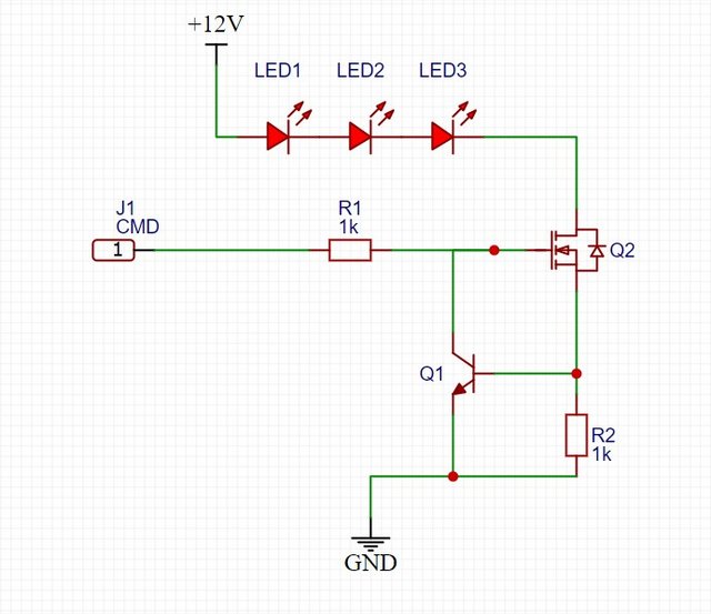
For 700 mA at about 600 mV, "R2" would be 0.82 Ohm. "R1" can indeed be 1k, is not critical as the voltage gain of the logic-level FET is very large. An IRFZ44 is not a logic-level FET and is unsuitable. An IRL540 would be suitable, will need a heatsink for linear operation as it may dissipate several Watts like the LEDs.
You need to define what you mean by "flickering"; I presume you mean stroboscopic flashing at a regular rate. Do you really want dimming? I presume you want the 12 LEDs to be distributed over a wider area of the visual field, so the obvious means of dimming by choosing to use one, two or four strings is not so practical.
Why do you think how fast the LEDs turn on or turn off matters?
Paul__B:
Indeed, you have done a lot of "talking".
You said four strings of three, which sounds about right for 12 V. You realise of course that you then need four separate constant current drivers.
For 700 mA at about 600 mV, "R2" would be 0.82 Ohm. "R1" can indeed be 1k, is not critical as the voltage gain of the logic-level FET is very large. An IRFZ44 is not a logic-level FET and is unsuitable. An IRL540 would be suitable, will need a heatsink for linear operation as it may dissipate several Watts like the LEDs.
You need to define what you mean by "flickering"; I presume you mean stroboscopic flashing at a regular rate. Do you really want dimming? I presume you want the 12 LEDs to be distributed over a wider area of the visual field, so the obvious means of dimming by choosing to use one, two or four strings is not so practical.
Why do you think how fast the LEDs turn on or turn off matters?
Thanks for the help.
By flickering I mean stroboscopic, at rates from 1Hz to 1kHz. With cyclical rate of 50%, or maybe adjustable.
To have a general idea, here is a product that is close to what I want :
So NO, the light won't be distributed in different directions.
They will all be in the same direction.
This is why I would appreciate having the possibility to regulate the LEDs intensity. In order for the user to choose.
I do realise that I need 4 separate drivers.
Why does a "logic level FET" is required ? What is it, exactly ?
How do you come up with V_R2 = 600 mV ?
I would say that I have 3*3.5 = 10.5V which gives 1.5V (if VDS = 0, which I am not sure of).
"Why do you think how fast the LEDs turn on or turn off matters?"
I don't understand the question here.
arthek:
Why does a "logic level FET" is required ? What is it, exactly ?
A "logic level FET" is one that can turn on fully with a logic level voltage, which means something less than 5 V or preferably, something less than 3.3 V since that is now the common logic supply voltage. The IRFZ44 only starts to turn on at something between 2 and 4 V, but requires 10 V on the gate before you can guarantee lowest resistance/ minimum voltage drop.
arthek:
How do you come up with V_R2 = 600 mV ?
That is the approximate voltage - Vbe - on the base of the transistor where it starts to conduct. When it conducts, it pulls down the gate of the FET to limit the current.
arthek:
I would say that I have 3*3.5 = 10.5V which gives 1.5V (if VDS = 0, which I am not sure of).
Well, in this circuit the source of the FET is already sitting at 600 mV when the current is regulated, so that takes part of your 1.5 V leeway, but the proper logic-level FET will pull Vds down to not too many millivolts.
arthek:
Why do you think how fast the LEDs turn on or turn off matters?
I don't understand the question here.
Why are you interested in "harsh stopping of the supply"?
Paul__B:
Nice, a bit pricey, but definitely no PWM!
:o Modules like that are designed for PWM.
The three PWM (on/off) inputs of that module can be used individually, or connected to one Arduino PWM pin.
Leo..
Paul__B:
A "logic level FET" is one that can turn on fully with a logic level voltage, which means something less than 5 V or preferably, something less than 3.3 V since that is now the common logic supply voltage. The IRFZ44 only starts to turn on at something between 2 and 4 V, but requires 10 V on the gate before you can guarantee lowest resistance/ minimum voltage drop.
Ok, great. Thank you.
Paul__B:
That is the approximate voltage - Vbe - on the base of the transistor where it starts to conduct. When it conducts, it pulls down the gate of the FET to limit the current.
Oh yes... Of course. Did not see that that way. Thanks.
When the Vbe>0.6 then the transistor conducts. Then the diode are not conducting anymore. Which is what I call "harsh stopping".
It will create a kind of high freq signal that drives the LED. Right ?
That signal will stack up to my LED driving signal (let's say 40Hz).
I am not sure I like that.
What do you think of the freewheeling solution with a diode ?
It will enable to supress the "oscillating" of the LEDs, by keeping them lighten.
Paul__B:
Why are you interested in "harsh stopping of the supply"?
arthek:
Why whould it be better than mosfet ?
Why 19V ?
I have 12V, I think it will do the job.
A switching constant current LED driver has high efficiency (no big/hot CL resistor), and will keep LED current constant independent of supply voltage (a mosfet + CL resistor does not).
12volt will be ok for three white/blue LEDs in series. Not for four.
The mosfet circuit needs some overhead voltage for the current limiting resistor.
So does a switching circuit, but more overhead voltage is not a problem for a switching circuit.
Leo..
arthek:
When the Vbe>0.6 then the transistor conducts. Then the diode are not conducting anymore. Which is what I call "harsh stopping".
It will create a kind of high freq signal that drives the LED. Right ?
No. This is referred to as "negative feedback". How much the transistor conducts and pulls down the FET gate will be proportional to how much the voltage on its base exceeds the conduction threshold. It will find a point where they balance out. The only reason it would oscillate would be where something caused a delay between the two effects.
arthek:
That signal will stack up to my LED driving signal (let's say 40Hz).
I am not sure I like that.
No such thing.
arthek:
What do you think of the freewheeling solution with a diode ?
It will enable to supress the "oscillating" of the LEDs, by keeping them lighten.
I am interested in NOT having it !
You appear to be rather confused about something here.
Wawa:
A switching constant current LED driver has high efficiency (no big/hot CL resistor), and will keep LED current constant independent of supply voltage (a mosfet + CL resistor does not).
12volt will be ok for three white/blue LEDs in series. Not for four.
The mosfet circuit needs some overhead voltage for the current limiting resistor.
So does a switching circuit, but more overhead voltage is not a problem for a switching circuit.
Leo..
Paul__B:
No. This is referred to as "negative feedback". How much the transistor conducts and pulls down the FET gate will be proportional to how much the voltage on its base exceeds the conduction threshold. It will find a point where they balance out. The only reason it would oscillate would be where something caused a delay between the two effects.
No such thing.
You appear to be rather confused about something here.
Indeed I have not played with transistor in a while. I was confused.
I forgot it was working in linear mode...
I know it is basic electronics... But I need to understand well !
Here is what I understand :
Q2 : I_LED depends on VGS
Q1 :
The more it conducts, the more VGS_Q2 decreases, so I_LED decreases.
When current exceeds 700mA, VBE>600mV.
Then ??? How/why does it impact collector current ?
I thought the transistor conduction was dependant on base current ?
I would like to make simulations to better understand. What tool can I use please ?
All of the LED current goes through R2, until the voltage across R2 increases and reaches the ~0.6volt base threshold of Q1. Then some of the current starts to (over)flow into the base.
Leo..