Hallo liebe Forumsmitglieder,
das Projekt Neuanfang habe ich zunächst zurückgestellt.
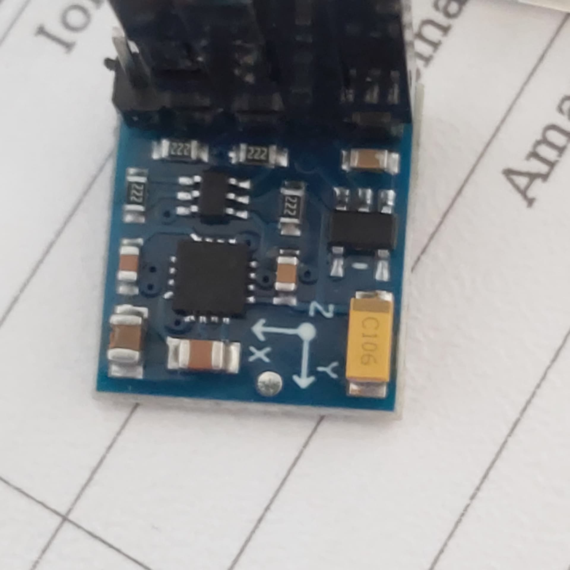
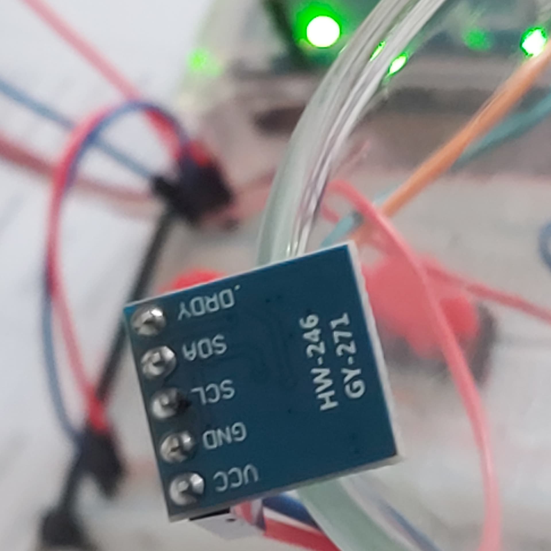
Hab aus meinen Sensoren den GY271 für die nächsten Versuche auserkoren.
Nun habe ich 3 sketche und keiner bringt das erwartete Ergebnis in die Serielle Ausgabe.
Ich habe die Codes zum kopieren jeweils um die Ausgaben erweitert,der I2c Scanner zeigt kein Ergebnis es werden aber Ausgaben gemacht????
Nr 1
// Kompass mit Kompass-Sensor HMC5883
// Datei: arduino-sensoren-2-kap6-kompass-hmc5583.ino

#include <Wire.h>
#include <HMC5883L.h>

float winkel;
int w;

// Kompass Objekt
HMC5883L compass;
// Fehler
int error = 0;


void setup()
{
   // Serielle Schnittstellen
  Serial.begin(9600);
  Wire.begin();
  Serial.print("Start Kompass mit HMC5883");

  // Skalierung setzen
  error = compass.setScale(1.3);
  // falls Fehler
  if(error != 0){
    Serial.println(compass.getErrorText(error));
  }
  // Continuous Mode setzen
  error = compass.setMeasurementMode(MEASUREMENT_CONTINUOUS);
  if(error != 0){
     Serial.println(compass.getErrorText(error));
  }
}


void loop()
{
  // Rohdaten einlesen
  MagnetometerRaw raw = compass.readRawAxis();
  // Skalierte Daten
  MagnetometerScaled scaled = compass.readScaledAxis();
  // Kalkulation
  float heading = atan2(scaled.YAxis, scaled.XAxis);

  // Ermittlung Magnetic Declination unter http://www.magnetic-declination.com/
  // Mein Wert: +2° 29' -> 2.48333° -> Rad 0.043342
  float declinationAngle = 0.0349066;
  heading += declinationAngle;

  // Korrektur wenn invertiert
  if(heading < 0)
    heading += 2*PI;
  // Limitierung Winkel
  if(heading > 2*PI)
    heading -= 2*PI;

  // Umrechnung Radiant zu Grad
  winkel = heading * 180/M_PI;

  // Winkel als Integer
  w = winkel;

  // Ausgabe Winkelgrad
  Serial.print("Winkel: ");
  Serial.println(w);

  delay(1000);

 // eingefügt I2c Scanner

  byte error, address;
  int nDevices;

  Serial.println("Scanning...");

  nDevices = 0;
  for(address = 1; address < 127; address++ )
  {
    // The i2c_scanner uses the return value of
    // the Write.endTransmisstion to see if
    // a device did acknowledge to the address.
    Wire.beginTransmission(address);
    error = Wire.endTransmission();

    if (error == 0)
    {
      Serial.print("I2C device found at address 0x");
      if (address<16)
        Serial.print("0");
      Serial.print(address,HEX);
      Serial.println("  !");

      nDevices++;
    }
    else if (error==4)
    {
      Serial.print("Unknown error at address 0x");
      if (address<16)
        Serial.print("0");
      Serial.println(address,HEX);
    }
  }
  if (nDevices == 0)
    Serial.println("No I2C devices found\n");
  else
    Serial.println("done\n");

}

/* Ausgabe Monitor
08:20:58.816 -> HMC5883 Magnetometer Test
08:20:58.848 ->
08:21:16.139 -> ------------------------------------
08:21:16.235 -> Sensor:       HMC5883
08:21:16.236 -> Driver Ver:   1
08:21:16.236 -> Unique ID:    12345
08:21:16.245 -> Max Value:    800.00 uT
08:21:16.270 -> Min Value:    -800.00 uT
08:21:16.270 -> Resolution:   0.20 uT
08:21:16.301 -> ------------------------------------
08:21:16.333 ->
08:21:16.788 -> X: -0.09  Y: -0.09  Z: -0.10  uT
08:21:16.820 -> Heading (degrees): 227.57

08:26:52.264 -> No I2C devices found
08:26:52.296 ->
08:26:52.296 -> Winkel: 89
08:26:53.269 -> Scanning...
08:26:53.303 -> No I2C devices found
08:26:53.303 ->
08:26:53.303 -> Winkel: 274
08:26:54.303 -> Scanning...
08:26:54.303 -> No I2C devices found
08:26:54.336 ->
08:26:54.336 -> Winkel: 90
08:26:55.303 -> Scanning...
08:26:55.335 -> No I2C devices found
*/
Nr 2
// Kompass mit LED-Anzeige
// Datei: arduino-sensoren-2-kap6-kompass-led.ino


/*****************************************************************************/
//	Function:	 Get the Geographic direction of the X-axis.
//				If X-axis points to the North, it is 0 degree.
//				If X-axis points to the East, it is 90 degrees.
//				If X-axis points to the South, it is 180 degrees.
//				If X-axis points to the West, it is 270 degrees.
//  Hardware:   Grove - 3-Axis Digital Compass
//	Arduino IDE: Arduino-1.0
//	Author:	 Frankie.Chu
//	Date: 	 Jan 10,2013
//	Version: v1.0
//	by www.seeedstudio.com
//
//  This library is free software; you can redistribute it and/or
//  modify it under the terms of the GNU Lesser General Public
//  License as published by the Free Software Foundation; either
//  version 2.1 of the License, or (at your option) any later version.
//
//  This library is distributed in the hope that it will be useful,
//  but WITHOUT ANY WARRANTY; without even the implied warranty of
//  MERCHANTABILITY or FITNESS FOR A PARTICULAR PURPOSE.  See the GNU
//  Lesser General Public License for more details.
//
//  You should have received a copy of the GNU Lesser General Public
//  License along with this library; if not, write to the Free Software
//  Foundation, Inc., 51 Franklin St, Fifth Floor, Boston, MA  02110-1301  USA
//
/*******************************************************************************/

#include <Wire.h>
#include <HMC5883L.h>

// Kompass Objekt
HMC5883L compass;
// Fehler
int error = 0;

// Wert Winkel
float headingDegrees;

// LED-Pins
int PinLED1 = 2;
int PinLED2 = 3;
int PinLED3 = 4;
int PinLED4 = 5;
int PinLED5 = 6;
int PinLED6 = 7;
int PinLED7 = 8;
int PinLED8 = 9;


void setup()
{
  // Ausgänge LED
  pinMode(PinLED1, OUTPUT);
  pinMode(PinLED2, OUTPUT);
  pinMode(PinLED3, OUTPUT);
  pinMode(PinLED4, OUTPUT);
  pinMode(PinLED5, OUTPUT);
  pinMode(PinLED6, OUTPUT);
  pinMode(PinLED7, OUTPUT);
  pinMode(PinLED8, OUTPUT);

  // Start serielle Schnittstelle
  Serial.begin(9600);

  Serial.println("Starting the I2C interface.");
  Wire.begin(); // Start the I2C interface.

  Serial.println("Constructing new HMC5883L");

  Serial.println("Setting scale to +/- 1.3 Ga");
  error = compass.setScale(1.3); // Set the scale of the compass.
  if(error != 0) // If there is an error, print it out.
    Serial.println(compass.getErrorText(error));

  Serial.println("Setting measurement mode to continous.");
  error = compass.setMeasurementMode(MEASUREMENT_CONTINUOUS); // Set the measurement mode to Continuous
  if(error != 0) // If there is an error, print it out.
    Serial.println(compass.getErrorText(error));
}


void loop()
{
  // Retrive the raw values from the compass (not scaled).
  MagnetometerRaw raw = compass.readRawAxis();
  // Retrived the scaled values from the compass (scaled to the configured scale).
  MagnetometerScaled scaled = compass.readScaledAxis();

  // Values are accessed like so:
  int MilliGauss_OnThe_XAxis = scaled.XAxis;// (or YAxis, or ZAxis)

  // Calculate heading when the magnetometer is level, then correct for signs of axis.
  float heading = atan2(scaled.YAxis, scaled.XAxis);

  // Once you have your heading, you must then add your 'Declination Angle', which is the 'Error' of the magnetic field in your location.
  // Find yours here: http://www.magnetic-declination.com/
  // Mine is: -2��37' which is -2.617 Degrees, or (which we need) -0.0456752665 radians, I will use -0.0457
  // If you cannot find your Declination, comment out these two lines, your compass will be slightly off.
  float declinationAngle = -0.0349;
  heading += declinationAngle;

  // Correct for when signs are reversed.
  if(heading < 0)
    heading += 2*PI;

  // Check for wrap due to addition of declination.
  if(heading > 2*PI)
    heading -= 2*PI;

  // Umrechnung Radiant zu Grad
  headingDegrees = heading * 180/M_PI;

  // Output the data via the serial port.
  //Output(raw, scaled, heading, headingDegrees);

  // Ansteuerung LED
  SetLED(headingDegrees);

  // Ausgabe Winkel
  Serial.print(headingDegrees);
  Serial.println(" Grad");

  delay(1000);
}


void SetLED(float headingDegrees)
{
  float w = headingDegrees;

  // Ausgabe des Winkels, Aktivierung der zugehörigen LED

  // LED1, 337.5 - 360, 0-22.5
  if (w > 337.5 &&  w < 361)
  {
    digitalWrite(PinLED1, HIGH);
  }
  else
  {
    digitalWrite(PinLED1, LOW);
  }
  if (w > 0 &&  w < 22.5)
  {
    digitalWrite(PinLED1, HIGH);
  }
   else
  {
    digitalWrite(PinLED1, LOW);
  }

  // LED2, 22.5-67.5
  if (w > 22.5 &&  w < 67.5)
  {
    digitalWrite(PinLED2, HIGH);
  }
  else
  {
    digitalWrite(PinLED2, LOW);
  }

  // LED3, 67.5-112.5
  if (w > 67.5 &&  w < 112.5)
  {
    digitalWrite(PinLED3, HIGH);
  }
  else
  {
    digitalWrite(PinLED3, LOW);
  }

  // LED4, 112.5-157.5
  if (w > 112.5 &&  w < 157.5)
  {
    digitalWrite(PinLED4, HIGH);
  }
  else
  {
    digitalWrite(PinLED4, LOW);
  }

  // LED5, 157.5-202.5
  if (w > 157.5 &&  w < 202.5)
  {
    digitalWrite(PinLED5, HIGH);
  }
  else
  {
    digitalWrite(PinLED5, LOW);
  }

  // LED6, 202.5-247.5
  if (w > 202.5 &&  w < 247.5)
  {
    digitalWrite(PinLED6, HIGH);
  }
  else
  {
    digitalWrite(PinLED6, LOW);
  }

  // LED7, 247.5-292.5
  if (w > 247.5 &&  w < 292.5)
  {
    digitalWrite(PinLED7, HIGH);
  }
  else
  {
    digitalWrite(PinLED7, LOW);
  }

  // LED8, 292.5-337.5
  if (w > 292.5 &&  w < 337.5)
  {
    digitalWrite(PinLED8, HIGH);
  }
  else
  {
    digitalWrite(PinLED8, LOW);
  }

}


/* Ausgabe Monitor
08:40:14.880 -> Starting the I2C interface.
08:40:14.880 -> Constructing new HMC5883L
08:40:14.880 -> Setting scale to +/- 1.3 Ga
08:40:16.353 -> Starting the I2C interface.
08:40:16.385 -> Constructing new HMC5883L
08:40:16.417 -> Setting scale to +/- 1.3 Ga
08:40:34.128 -> Setting measurement mode to continous.
08:40:34.219 -> 86.53 Grad
08:40:35.160 -> 86.53 Grad
08:40:36.160 -> 86.53 Grad
08:40:37.161 -> 86.53 Grad
08:40:38.159 -> 86.53 Grad
08:40:39.158 -> 86.53 Grad
08:40:40.157 -> 86.53 Grad
*/
Wenn ich den Sensor auf dem Tisch rotiere ändert sich nichts.
Wo ist mein Denkfehler ??
Nr 3
/***************************************************************************
  This is a library example for the HMC5883 magnentometer/compass

  Designed specifically to work with the Adafruit HMC5883 Breakout
  http://www.adafruit.com/products/1746

  *** You will also need to install the Adafruit_Sensor library! ***

  These displays use I2C to communicate, 2 pins are required to interface.

  Adafruit invests time and resources providing this open source code,
  please support Adafruit andopen-source hardware by purchasing products
  from Adafruit!

  Written by Kevin Townsend for Adafruit Industries with some heading example from
  Love Electronics (loveelectronics.co.uk)

 This program is free software: you can redistribute it and/or modify
 it under the terms of the version 3 GNU General Public License as
 published by the Free Software Foundation.

 This program is distributed in the hope that it will be useful,
 but WITHOUT ANY WARRANTY; without even the implied warranty of
 MERCHANTABILITY or FITNESS FOR A PARTICULAR PURPOSE.  See the
 GNU General Public License for more details.

 You should have received a copy of the GNU General Public License
 along with this program.  If not, see <http://www.gnu.org/licenses/>.

 ***************************************************************************/

#include <Wire.h>
#include <Adafruit_Sensor.h>
#include <Adafruit_HMC5883_U.h>

/* Assign a unique ID to this sensor at the same time */
Adafruit_HMC5883_Unified mag = Adafruit_HMC5883_Unified(12345);

void displaySensorDetails(void) {
  sensor_t sensor;
  mag.getSensor(&sensor);
  Serial.println("------------------------------------");
  Serial.print("Sensor:       ");
  Serial.println(sensor.name);
  Serial.print("Driver Ver:   ");
  Serial.println(sensor.version);
  Serial.print("Unique ID:    ");
  Serial.println(sensor.sensor_id);
  Serial.print("Max Value:    ");
  Serial.print(sensor.max_value);
  Serial.println(" uT");
  Serial.print("Min Value:    ");
  Serial.print(sensor.min_value);
  Serial.println(" uT");
  Serial.print("Resolution:   ");
  Serial.print(sensor.resolution);
  Serial.println(" uT");
  Serial.println("------------------------------------");
  Serial.println("");
  delay(500);
}

void setup(void) {
  Serial.begin(9600);
  Serial.println("HMC5883 Magnetometer Test");
  Serial.println("");

  /* Initialise the sensor */
  if (!mag.begin()) {
    /* There was a problem detecting the HMC5883 ... check your connections */
    Serial.println("Ooops, no HMC5883 detected ... Check your wiring!");
    while (1)
      ;
  }

  /* Display some basic information on this sensor */
  displaySensorDetails();
}

void loop(void) {
  /* Get a new sensor event */
  sensors_event_t event;
  mag.getEvent(&event);

  /* Display the results (magnetic vector values are in micro-Tesla (uT)) */
  Serial.print("X: ");
  Serial.print(event.magnetic.x);
  Serial.print("  ");
  Serial.print("Y: ");
  Serial.print(event.magnetic.y);
  Serial.print("  ");
  Serial.print("Z: ");
  Serial.print(event.magnetic.z);
  Serial.print("  ");
  Serial.println("uT");

  // Hold the module so that Z is pointing 'up' and you can measure the heading with x&y
  // Calculate heading when the magnetometer is level, then correct for signs of axis.
  float heading = atan2(event.magnetic.y, event.magnetic.x);

  // Once you have your heading, you must then add your 'Declination Angle', which is the 'Error' of the magnetic field in your location.
  // Find yours here: http://www.magnetic-declination.com/
  // Mine is: -13* 2' W, which is ~13 Degrees, or (which we need) 0.22 radians
  // If you cannot find your Declination, comment out these two lines, your compass will be slightly off.
     float declinationAngle = 0.0449066;
     heading += declinationAngle;

  // Correct for when signs are reversed.
  if (heading < 0)
    heading += 2 * PI;

  // Check for wrap due to addition of declination.
  if (heading > 2 * PI)
    heading -= 2 * PI;

  // Convert radians to degrees for readability.
  float headingDegrees = heading * 180 / M_PI;


  Serial.print("Heading (degrees): ");
  Serial.println(headingDegrees);

  delay(1000);
}

/* Ausgabe des Monitors
08:20:58.848 ->
08:21:16.139 -> ------------------------------------
08:21:16.213 -> Sensor:       HMC5883
08:21:16.214 -> Driver Ver:   1
08:21:16.214 -> Unique ID:    12345
08:21:16.239 -> Max Value:    800.00 uT
08:21:16.270 -> Min Value:    -800.00 uT
08:21:16.271 -> Resolution:   0.20 uT
08:21:16.301 -> ------------------------------------
08:21:16.333 ->
08:21:16.788 -> X: -0.09  Y: -0.09  Z: -0.10  uT
08:21:16.820 -> Heading (degrees): 227.57
08:21:17.792 -> X: -0.09  Y: -0.09  Z: -0.10  uT
08:21:17.826 -> Heading (degrees): 227.57
08:21:18.794 -> X: -0.09  Y: -0.09  Z: -0.10  uT
08:21:18.827 -> Heading (degrees): 227.57
08:21:19.796 -> X: -0.09  Y: -0.09  Z: -0.10  uT
*/
Nr 3 ist der Beispielcode den ich um den I2c Scanner erweitert habe,
wo ist es sinnig weiterzumachen?
Text ab hier Bearbeitet 24.3.25 11:55
Der Sensor ist nur mit dem Uno direkt verbunden.
VCC -- VCC
GND -- GND
SLC -- SLC
SDA -- SDA
Wenn im laufenden Betrieb SLC und SDA getauscht werden erfolgt Trotzdem eine Ausgabe im Monitor .
mfg
Walter