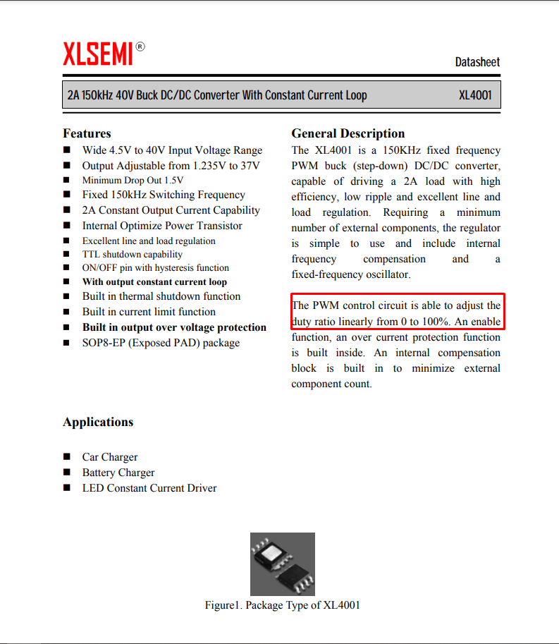
Hello, everyone! I'm trying to make a dimmable LED lamp for aquariums and, for about a month now, I'm trying to come up with a driver for the LEDs. I made some research and ended up finding a LED driver shield that uses the XL4001E1 IC to control 3W LEDs with PWM.

(Source: Next best pwm LED driver? xl4001e1 0-40v 2a - Lighting Forum - Nano-Reef Community)
I've bought one of those about 6 months ago, but, unfortunatelly, the shipping price of those shields to my country makes them too expensive for me to aford (I would need 5 of them). So, for that reason, I decided to make my own driver. I've bought the IC (XL4001E1 - https://datasheet.lcsc.com/lcsc/1811021113_XLSEMI-XL4001E1_C73347.pdf) and used some adpaters to make them suitable for my breadboard. I followed the instructions on the datasheet for LED constant current driver and used the enable pin to control the PWM (since this is how PWM control is handled on the shield I've bought before).

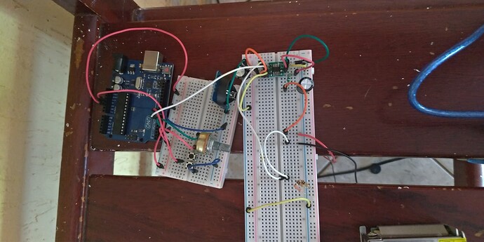
This is the circuit I came up with:
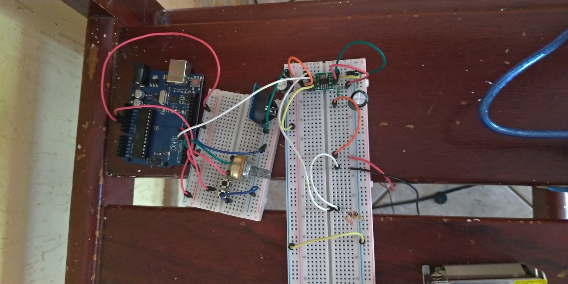
Since the breadboard photo looks absolutely terrible, here is the schematics:

With this circuit, I can turn on the LEDs, but i'm having a hard time controlling their brightness. On the datasheet, it's said that driving the enable pin high turns the LEDs off:
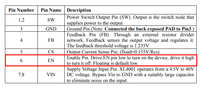
The thing is: when I connect the enable pin directly to VCC or to a pin set to high through "digitalWrite (6, HIGH)", it turns off. But when I try to control it using PWM (I tried using a potentiometer to control the PWM on pin 6, for example), the LEDs won't change brightness and won't even turn off. If I set the PWM voltage to 5V using the potentiometer, when I measure the voltage on the enable pin (on the IC), it reads 5V (the same voltage that makes it turn off when I connect directly to VCC or to a pin set to high using digitalWrite) but the LEDs are still on and shining brightly. At first, I thought that the problem was that I was using 12 VCC to power up the IC and 5 VCC to control the PWM, but, since I can turn the LEDs off using direct 5 VCC from Arduino, I've discarded this idea. Also, the shield that uses this same IC, has the exact same circuit: the PWM goes into the enable pin and the GND from Arduino and the source are shared. And the shield works perfectly. In the end, I even bought components with the exat same values as the ones used in the shield to test if they influenced something, but nothing changed. I have no idea what I have done wrong and I finally decided that I need help. I've tried everything but can't understand what is wrong with my circuit. Thanks in advance!