Im able to change the duty cycle and the frequency of a 3 pwm signals. But I still need to change the amplitude of each PWM signal can anyone tell me how to make do it ?
#include "asf.h"
#include "conf_board.h"
#include "conf_clock.h"

/** PWM frequency in Hz */
#define PWM_FREQUENCY      800
/** Period value of PWM output waveform */
#define PERIOD_VALUE       100
/** Initial duty cycle value */
#define INIT_DUTY_VALUE    50


/* PIN Definition for the third PWM Channel @ Arduino Due Board = PWM  PIN 07 */
#define PIN_PWM_3DPWM_GPIO     PIO_PC23_IDX
#define PIN_PWM_3DPWM_FLAGS   (PIO_PERIPH_B | PIO_DEFAULT)
#define PIN_PWM_3DPWM_CHANNEL PWM_CHANNEL_6


/** PWM channel instance  */
pwm_channel_t g_pwm_channel_led;

/**
 * \brief Interrupt handler for the PWM controller.
 */
void PWM_Handler(void)
{
	static uint32_t ul_count = 0;  /* PWM counter value */
	static uint32_t ul_duty = INIT_DUTY_VALUE;  /* PWM duty cycle rate */
	static uint8_t fade_in = 1;  /* LED fade in flag */
	uint32_t events = pwm_channel_get_interrupt_status(PWM);

	/* Interrupt on PIN_PWM_LED0_CHANNEL */
	if ((events & (1 << PIN_PWM_LED0_CHANNEL)) ==
			(1 << PIN_PWM_LED0_CHANNEL)) {
		ul_count++;

		/* Fade in/out */
		if (ul_count == (PWM_FREQUENCY / (PERIOD_VALUE - INIT_DUTY_VALUE))) {
			/* Fade in */
			if (fade_in) {
				ul_duty = INIT_DUTY_VALUE;
				if (ul_duty == PERIOD_VALUE) {
					fade_in = 0;
				}
			} else {
				/* Fade out */
				ul_duty = INIT_DUTY_VALUE;
				if (ul_duty == INIT_DUTY_VALUE) {
					fade_in = 1;
				}
			}

			/* Set new duty cycle */
			ul_count = 0;
			g_pwm_channel_led.channel = PIN_PWM_LED0_CHANNEL;
			pwm_channel_update_duty(PWM, &g_pwm_channel_led, ul_duty);
			g_pwm_channel_led.channel = PIN_PWM_LED1_CHANNEL;
			pwm_channel_update_duty(PWM, &g_pwm_channel_led, ul_duty);

			g_pwm_channel_led.channel = PIN_PWM_3DPWM_CHANNEL;
			pwm_channel_update_duty(PWM, &g_pwm_channel_led, ul_duty);
		}
	}
}


int main(void)
{
	/* Initialize the SAM system */
	sysclk_init();
	board_init();

	gpio_configure_pin(PIN_PWM_3DPWM_GPIO, PIN_PWM_3DPWM_FLAGS);  // for PWM PIN 3

	/* Enable PWM peripheral clock */
	pmc_enable_periph_clk(ID_PWM);

	/* Disable PWM channels for LEDs */
	pwm_channel_disable(PWM, PIN_PWM_LED0_CHANNEL);
	pwm_channel_disable(PWM, PIN_PWM_LED1_CHANNEL);
	pwm_channel_disable(PWM, PIN_PWM_3DPWM_CHANNEL);// 3rd PWM output

	/* Set PWM clock A as PWM_FREQUENCY*PERIOD_VALUE (clock B is not used) */
	pwm_clock_t clock_setting = {
		.ul_clka = PWM_FREQUENCY * PERIOD_VALUE,
		.ul_clkb = 0,
		.ul_mck = sysclk_get_cpu_hz()
	};
	pwm_init(PWM, &clock_setting);

	/* Initialize PWM channel for LED0 */
	/* Period is left-aligned */
	g_pwm_channel_led.alignment = PWM_ALIGN_LEFT;
	/* Output waveform starts at a low level */
	g_pwm_channel_led.polarity = PWM_LOW;
	/* Use PWM clock A as source clock */
	g_pwm_channel_led.ul_prescaler = PWM_CMR_CPRE_CLKA;
	/* Period value of output waveform */
	g_pwm_channel_led.ul_period = PERIOD_VALUE;
	/* Duty cycle value of output waveform */
	g_pwm_channel_led.ul_duty = INIT_DUTY_VALUE;
	g_pwm_channel_led.channel = PIN_PWM_LED0_CHANNEL;
	pwm_channel_init(PWM, &g_pwm_channel_led);

	/* Enable channel counter event interrupt */
	pwm_channel_enable_interrupt(PWM, PIN_PWM_LED0_CHANNEL, 0);

	/* Initialize PWM channel for LED1 */
	/* Period is center-aligned */
	g_pwm_channel_led.alignment = PWM_ALIGN_LEFT;
	/* Output waveform starts at a high level */
	g_pwm_channel_led.polarity = PWM_LOW;
	/* Use PWM clock A as source clock */
	g_pwm_channel_led.ul_prescaler = PWM_CMR_CPRE_CLKA;
	/* Period value of output waveform */
	g_pwm_channel_led.ul_period = PERIOD_VALUE;
	/* Duty cycle value of output waveform */
	g_pwm_channel_led.ul_duty = INIT_DUTY_VALUE;
	g_pwm_channel_led.channel = PIN_PWM_LED1_CHANNEL;
	pwm_channel_init(PWM, &g_pwm_channel_led);


	/* Initialize PWM channel for LED2 */
	/* Period is center-aligned */
	g_pwm_channel_led.alignment = PWM_ALIGN_LEFT;
	/* Output waveform starts at a high level */
	g_pwm_channel_led.polarity = PWM_LOW;
	/* Use PWM clock A as source clock */
	g_pwm_channel_led.ul_prescaler = PWM_CMR_CPRE_CLKA;
	/* Period value of output waveform */
	g_pwm_channel_led.ul_period = PERIOD_VALUE;
	/* Duty cycle value of output waveform */
	g_pwm_channel_led.ul_duty = INIT_DUTY_VALUE;
	g_pwm_channel_led.channel = PIN_PWM_3DPWM_CHANNEL;
	pwm_channel_init(PWM, &g_pwm_channel_led);


	/* Disable channel counter event interrupt */
	pwm_channel_disable_interrupt(PWM, PIN_PWM_LED1_CHANNEL, 0);

	/* Configure interrupt and enable PWM interrupt */
	NVIC_DisableIRQ(PWM_IRQn);
	NVIC_ClearPendingIRQ(PWM_IRQn);
	NVIC_SetPriority(PWM_IRQn, 0);
	NVIC_EnableIRQ(PWM_IRQn);

	/* Enable PWM channels for LEDs */
	pwm_channel_enable(PWM, PIN_PWM_LED0_CHANNEL);
	pwm_channel_enable(PWM, PIN_PWM_LED1_CHANNEL);
	pwm_channel_enable(PWM, PIN_PWM_3DPWM_CHANNEL);

	/* Infinite loop */
	while (1) {
	}
}
Im able to change the duty cycle and the frequency of a 3 pwm signals. But I still need to change the amplitude of each PWM signal can anyone tell me how to make do it ?
Are you saying you want to level shift an PWM output to 5V ??? We never talk
of amplitude for a logic signal, that's reserved for analog signals.
I just need to variy it like having 10% of the 3.3v or 50% esc.
So no external hardware or so
I attached my code at the first thrid I posted so can aye one tell me wht I need to be able to vary the aplitude of the pwm signal from 0v till max 3.3 volt ?
CrossRoads:
You get 0V, you get 3.3V. That's it. You want a level in between you need external hardware. 2 resistors as a voltage divider as minimum.
I believe the Due actually has two digital to analog converters (as opposed to just PWM), which can be used to provide a changing voltage at the output pin. With these there really isn't a need for PWM, and no external hardware is needed, PB15 & PB16
No, what I was saying is that if someone needs a specific voltage on an output pin, without using external components, the two DACS that are available are perfect for that application. And this is unique to the Due among the Arduino boards I believe.
I'm not sure why someone would need an arbitrary voltage AND PWM...
I just need to variy it like having 10% of the 3.3v or 50% esc.
So no external hardware or so
I attached my code at the first thrid I posted so can aye one tell me wht I need to be able to vary the aplitude of the pwm signal from 0v till max 3.3 volt ?
Thanks in advance
Perhaps if you can explain what you will do with this PWM signal of variable amplitude we can better understand. What will you be wiring to this signal?
well I have now 3 pwm signals with a variable duty cycle and frequency and my next step it to overly a sine array to my pwm so that I can get a have a sine pwm.. then I will need an Interrupt to control the sine wave frequency but I still dont know exactly how to make it . I would be thankfull if anyone can help me with me further steps
I may be wrong but i think what was being asked was what you intended to use your pwm sine wave for.
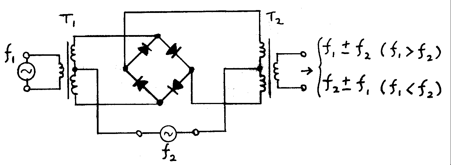
After reading your explaination, it sounds like you are trying to mix two frequencies, kind of like what is done when digital signals are imposed on an AC voltage line. Some research on that subject might help you. One such example is the old X-10 protocol.
Hi I try to devolp an H bridge with 6 Mosfets in order to use them to drive a 3 phase electrical motor... there for I need to rebuild 3x sine waves through varing the PWM signal
If you use a h-bridge driver chip designed for 3-phase motors you eliminate the need to send complicated sine waves to the motor. Something like the TI DRV8313 is controlled solely through three sets of digital signals (look at the control waveforms in the datasheet). One of which (for each phase) can be a PWM signal to control the motors speed.
Thanks for your reply I know that I can use such a chip but I want to use the Arduino due to devolp the h bridge and it is possible without any external chips
Yes it is possible without any external CHIPS, but then you need to use a variety of parts to emulate the function of the chip. It is absolutely IMPOSSIBLE to control even a tiny motors speed and direction with only a MCU. It will be easier and cheaper to use a purpose built chip; however, if you want to do it as an educational exercise then I highly suggest starting with a h-bridge circuit for a standard small motor (not 3-phase).
Well instead of telling me that it will not work- Can just anyone help me solving my problem ! I posted
I just want to add a sine array to my pwm generator code i Posted but I actually dont know how exactly can some one give me a usefull tip not like those from gumpy mike ?
You have already been given several useful tips, not the least of which is that you must use some external components to accomplish your goal. That is a fact of nature. For more details look at any of the data sheets for the chips that do what you want and notice how those implementations solve the problem.
After you convert your PWM outputs to actual analog signals, then there are several ways such signals can be mixed.