I used 8 byte for now instead of 32 bytes. And I send each byte individually and still byte 2 and 3 are missing, I also tried sending only these missing bytes however, the output is like a garbage it produces diff ascii output every time I try to reset and rerun the code.
I tried this code also:
void setup() {
  Serial.begin(9600);
}
uint8_t byte2 = 0x90;
uint8_t byte3 = 0x80;

void loop() {
  Serial.write(byte2);
  Serial.write(byte3);
  Serial.flush();
  delay(100);
}
I tried sending byte 2 and 3 only with different value 0x90 and 0x80 but the result is € which is 20AC in hex.
With this code,
void setup() {
  Serial.begin(9600);
}
uint8_t header = 0xFF; // byte 0
uint8_t address = 0xFA; // byte 1
uint8_t byte2 = 0x90;
uint8_t byte3 = 0x80;
uint8_t byte4 = 0x34;
uint8_t byte5 = 0x56;
uint8_t byte6 = 0x00;
uint8_t checksum = 0xFA + 0x10 + 0x12 + 0x34 + 0x56 + 0x00;

void loop() {
  Serial.write(header);
  Serial.write(address);
  Serial.write(byte2);
  Serial.write(byte3);
  Serial.write(byte4);
  Serial.write(byte5);
  Serial.write(byte6);
  Serial.write(checksum);
  Serial.flush();
  delay(100);
}
I also tried sending an 8 bytes with 0x90 and 0x80 as the byte2 and 3 just to check what would the output be, and byte2 and byte3 is not missing but the output is incorrect it shows this ÿú€4V¦ if converted to hex is FF FA 20AC 34 56 A6.
How can I log the received data I'm only using PuTTY and I am using it's monitor to see what the output of my ESP is.
Using a search engine, I found this (among many others). Going beyond point 8 isn't relevant to your situation.
But PuTTY is an ASCII only terminal, not the best to display binary transmission. I suggest using a Hex capable terminal such as realterm or Coolterm
I think I used wrong wording of "how can I log" what I mean is what is its significance. And I agree I could search for other serial terminal, just wanted to clarify where is the part you are pointing of "going beyond point 8"
The link I provided explaining how to log using puTTY described it in 13 steps. Steps 9 and beyond are irrelevant to your situation.
But Coolterm is the way to go I think...
Oh I thought you are pointing out my code that is going beyond point 8 
I also have RealTerm but I'll study coolterm and try to use it. Will update here in a little while. Thank you again for being there to guide me through this, it helps a lot really.
Realterm is also suitable but it often crashes on my computer
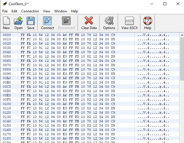
This is the output of this code on CoolTerm:
void setup() {
  Serial.begin(9600);
  // pinMode(TX_PIN, OUTPUT);
}
  uint8_t header = 0xFF; // byte 0
  uint8_t address1 = 0xFA; // byte 1
  uint8_t address2 = 0xFB;
  uint8_t address3 = 0xFC;
  uint8_t address4 = 0xFD;
  uint8_t byte2 = 0x10;
  uint8_t byte31 = 0x56;
  uint8_t byte32 = 0x78;
  uint8_t byte33 = 0x91;
  uint8_t byte34 = 0x82;
  uint8_t byte4 = 0x12;
  uint8_t byte5 = 0x34;
  uint8_t byte6 = 0x00;

  uint8_t checksum1 = address1 + byte2 + byte31 + byte4 + byte5 + byte6;
  uint8_t checksum2 = address2 + byte2 + byte32 + byte4 + byte5 + byte6;
  uint8_t checksum3 = address3 + byte2 + byte33 + byte4 + byte5 + byte6;
  uint8_t checksum4 = address4 + byte2 + byte34 + byte4 + byte5 + byte6;

void loop() {
  uint8_t data1[8] = {header, address1, byte2, byte31, byte4, byte5, byte6, checksum1};
  uint8_t data2[8] = {header, address2, byte2, byte32, byte4, byte5, byte6, checksum2};
  uint8_t data3[8] = {header, address3, byte2, byte33, byte4, byte5, byte6, checksum3};
  uint8_t data4[8] = {header, address4, byte2, byte34, byte4, byte5, byte6, checksum4};


  Serial.write(data1, sizeof(data1));
  Serial.write(data2, sizeof(data2));
  Serial.write(data3, sizeof(data3));
  Serial.write(data4, sizeof(data4));
  Serial.flush();

  delay(100); // wait for a second before sending the next command
}
With this, it means that the data are correctly sent, so does it have something to do with the pins on my ESP? I am still not quite sure of the declaration of pin number or is the code generally is correct or not.
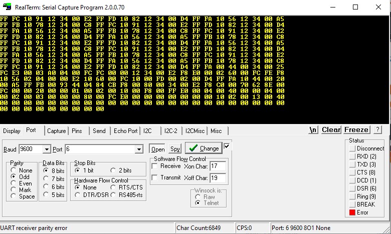
Hi I think I just made a progress. I have attached a usb to rs485 cable and connected it to my transceiver and used realterm to check the transceiver's output.
Base from the 1st picture, it has a result with my expected output, however after few seconds the result became like the 2nd and 3rd pic.
And now when I try to connect the transceiver again, from the start it says an error (just like the bottom right part of my 2nd picture) and no output on realterm.
Try to use Coolterm instead, Realterm has moods in my opinion (or maybe I don't use it properly...)
I always have a problem with the coolterm it always have this warning when I try to read the output of my transceiver.

Maybe it's due to baudrate or port configuration, check it.
If not, do you have an other Arduino that could receive the RS485 messages (no need of transceivers if you have only one) and send them to a serial terminal.
Or simply connect to your LEDs and try various commands...
About the baudrate, if I first use realterm it sometimes output the expected output, and right away it causes error. So if I try coolterm to check the output, from the start framing error already pops out.
Unfortunately, I don't have extra Arduino and connecting it to LED sometimes output a garbage display or sometimes no display at all.
What is the baudrate and protocol configured in coolterm ?
I am always using a 9600 baudrate and for the protocol config I use 8bits,even parity, 2 stops and I sometimes use 8bits, no parity, 1 stop.
??!! That's is not the way you configured the Arduino !
EDIT : On top of that, looking at the screen captures post #59, I see Odd parity, One Stop bit !!!
And when I say (post #33)
you don't mention you want to use parity...
First, what is the protocol required by your RS485 LED assembly ? It's the one you will have to comply with. Do you have their datasheet or at least their part number ?
To address your comment on post#66, I am trying to experiment and change the configuration from time to time, with this I also update the code like Serial.begin(9600, 8E2) if I am trying 8bit, even parity, 2 stop. I also change it to 8O1 if odd parity and 1 stop.
And there is no official datasheet nor part number info what I only have is the data format.
I don't know what happened maybe i just reconnect the wires and tied the reset wire on esp and pulled it up high after, but now, realterm is dispalying the output of transceiver.
But I also tried bypassing the transceiver and connected the tx pin of my ESP to the microcontroller of the LED which is ATmega169P's pin2 which is the RX pin. (I only tried this because I just think it might work)
However, still no display.
No, all serial port are compatible, even software serial. But I strongly suggest you use serial (as in serial.begin()) for debugging, and serial1 (or serial2, depending of your compiler's complaints) for the LEDs.
The thing you will have to discover is baudrate and protocol from the LEDs. As it uses a micro-controller, maybe it sends a welcome message at startup.
Connect it directly to your transceiver set to 19200 baud, 8N1 and power your LEDs up. Does it send a message of any sort. If the message is too long, try slower baud rate, if too short, faster baud rate. All of this is a guess work. You can tinker with protocol too but I doubt it's different from 8N1.
If no message, send one that is meaningful for the LEDs. Does it respond accordingly ? Each time it fails, power cycle the LEDs to empty its input buffer and try a different baudrate.
If you don't know how to send binary messages using your transceiver, do it through the Arduino with ready-made messages (2 of them alternatively should be OK). Write a sketch that send messages at baudrates from ranging from 9600 up to 115200 at the push of a button or at reception of a message (from serial). Power cycle mandatory here as well.