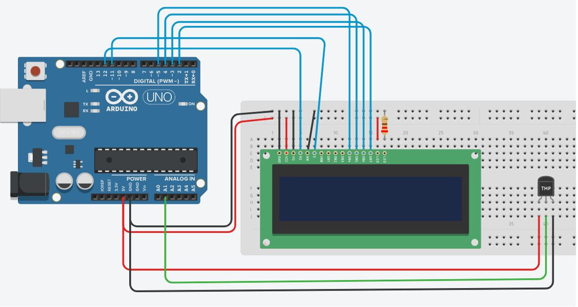
I am following the below website to build a project that will read the temperature using a TMP36 sensor and display it on an LCD 16 X 2 display.
According to the schematic diagram below, there are two pins that need connected into the 5V port and then two pins into one of the GND ports. I am unsure of how to do this as to me it seems as though you can physically only connect one pin at a time to a port?
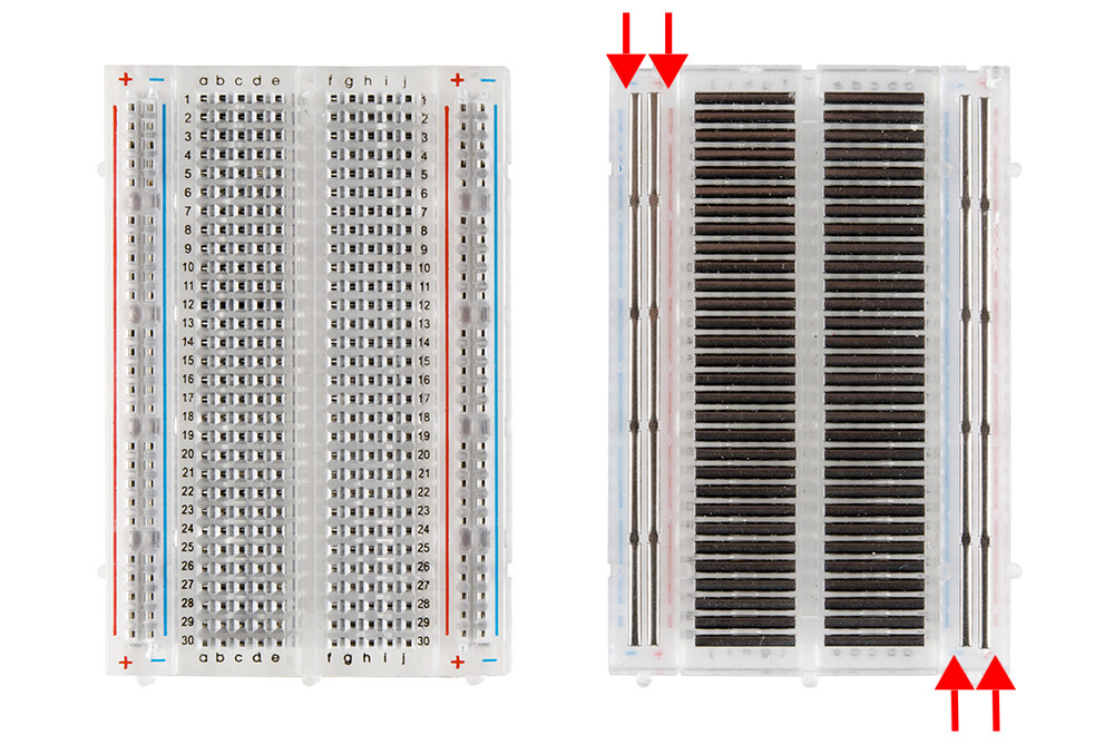
Use the power rails on the breadboard to expand the number of 5V and GND connections available, as in the picture, and connect the power lines of the temperature sensor to them
Also keep in mind that TMP36 requires very low current to operate (~50 uA). So eventually you can connect its VCC to any digital pin set to OUTPUT,HIGH and its GND to any digital pin set to OUTPUT,LOW.
The breadboard has groups of 5 contacts in columns and each of the contacts in a column are joined together. This allows components such as an LCD display to be plugged into adjacent columns and for connections to be made to its pins
The breadboard also has long rows of contacts that run along the edges of the breadboard and although they are in groups of 5 all of the contacts in each row are connected together (*** see below). This allows you to use them as power rails to distribute power to the components plugged into the breadboard as most require power
*** there are exceptions to this rule as some breadboards have a break in the centre of each row to allow multiple voltage rails to be used. This is usually obvious because the connected contacts in the rows are denoted by a solid line joining them and the centre break is then obvious