I have what looks like a rotary encoder and I'd like to reverse engineer it so that I can understand what signal it is sending to the device.
This "rotary encoder" has 5 pins on it. 2 of the pins are for the switch when you depress the dial and the other 3 for output A, output B and ground.
I the breakout board that the rotary encoder is connected to has a 4 pin socket and 4 wire ribbon that connects to the device. What is even stranger is that the breakout board only has 3 tracks that connect to the socket. Please note that the device does use the switch on the rotary encoder.
I have been learning and watching tutorials on rotary encoders but they always seem to use 4 pins and I kind of understand how they work. I don't understand how this would work with only 3 pins used and still be able to use the switch and and tell the difference between clockwise and counter clockwise?!?
How does this rotary encoder work with only 3 pins used?
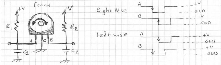
You didn’t give us the part number so one can only guess. Imagine if you attached the GND pin to ground and each of the remaining two pins to 5V through a 10k resistor. If the encoder part is two mechanical switches arranged so that they close 90º out of phase when the shaft is turned what would the output look like?
Emily, there are no part numbers on the encoder, I de-soldered it and couldn't see any numbers on the encoder at all. There are numbers on the breakout board (JT6.352.035V3.0 and 2017901) but nothing seemed to come up on a google search for it.
I think I may have made a mistake here as the single pin on the socket IS connected to a pin on the encoder - for some reason I just cannot find the track ....
As far as the output goes, I hadn't got to that stage as I couldn't find any info on how to wire it up. All the tutorials I has saw shows a VCC pin on the breakout board but don't seem to show VCC on the rotary encoder without the breakout board, confusing
I had a look at this link but it only seems to show VCC on a arduino breakout board, I trying to figure out where VCC would go direct without the breakout board
It worked! Just want to say thanks to everyone for helping here. I followed the schematic to mimic the breakout board and connected it with some 460 ohm resistors (I didn't have any 10k).
I used this code:
   read a rotary encoder with interrupts
   Encoder hooked up with common to GROUND,    encoder0PinA to pin 2, encoder0PinB to pin 4
   it doesn't matter which encoder pin you use for A or B
*/

#define encoder0PinA  2  //CLK Output A Do not use other pin for clock as we are using interrupt
#define encoder0PinB  4  //DT Output B
#define Switch 5 // Switch connection if available

volatile unsigned int encoder0Pos = 0;

void setup() {

  pinMode(encoder0PinA, INPUT);
  digitalWrite(encoder0PinA, HIGH);       // turn on pullup resistor
  pinMode(encoder0PinB, INPUT);
  digitalWrite(encoder0PinB, HIGH);       // turn on pullup resistor
  attachInterrupt(0, doEncoder, RISING); // encoder pin on interrupt 0 - pin2
  Serial.begin (9600);
  Serial.println("start");                // a personal quirk
}

void loop(){
// do some stuff here - the joy of interrupts is that they take care of themselves
  Serial.print("Position:");
  Serial.println (encoder0Pos, DEC);  //Angle = (360 / Encoder_Resolution) * encoder0Pos
}

void doEncoder() {
  if (digitalRead(encoder0PinB)==HIGH) {
    encoder0Pos++;
  } else {
    encoder0Pos--;
  }
}
type or paste code here
I was able to get a reading in the monitor. I was able to see incremental changes although it started from 65535 then it went up or down by 1.
I have a question now... Am I able to use an ardiuno inplace of a rotary encoder? Like is it possible to mimic the signals of the encoder? This is all so that I can control the device without touching the rotary enoder