While wiring the BLDC, I re-planned the circuitry of the wind generator.
It is one step forward to integration with the PV component: the output is to be connected via SW5 to the same battery as the PV charger.
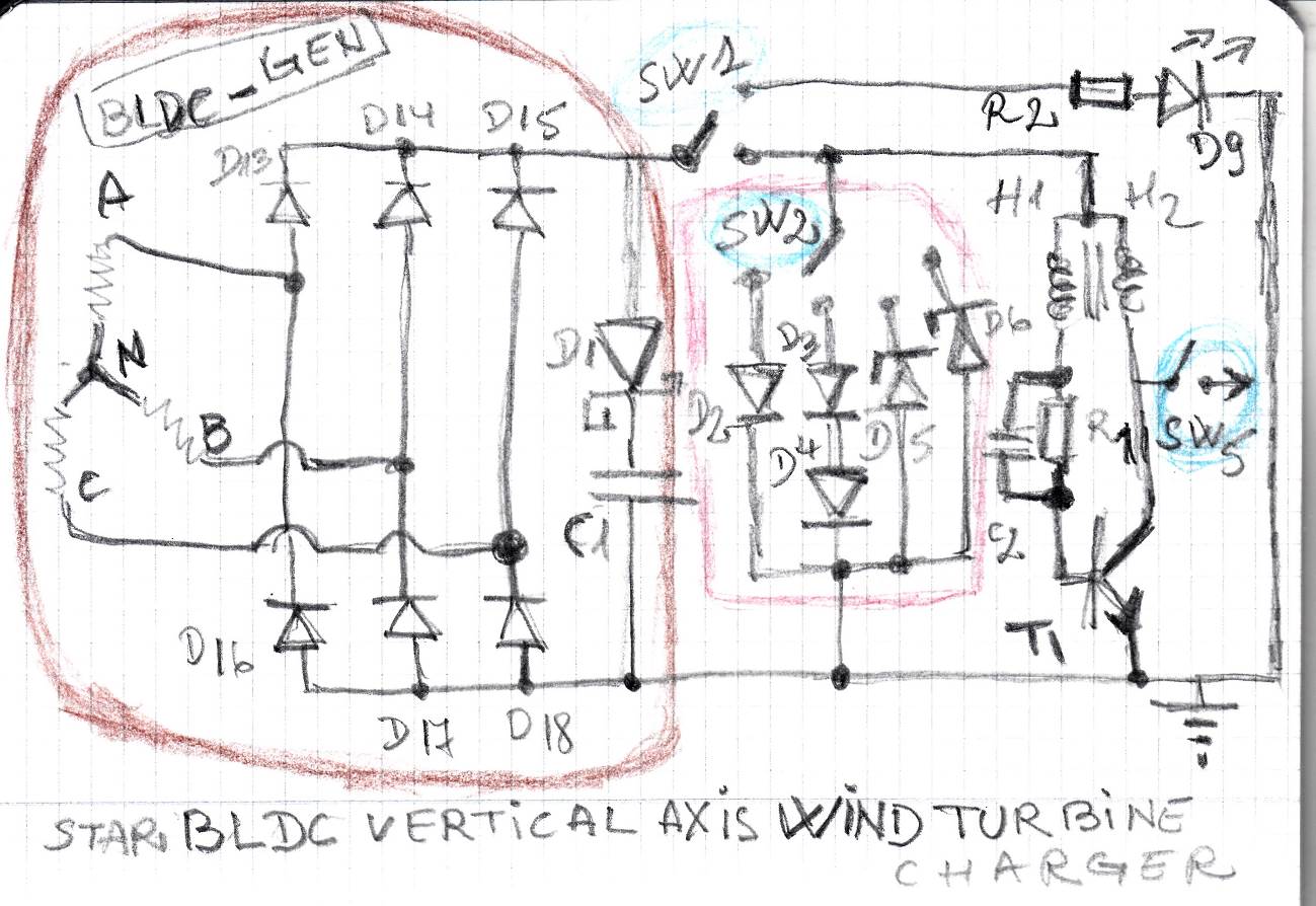
Here it is:
In brown, the BLDC and corresponding rectifier.
In red, the step by step voltage regulator for the Joule thief to function.
This is a demo project for kids, simplicity is more important than efficiency. Only passive components, diodes and transistors are allowed.
The PV component is completed, tested in field and is OK.
The Arduino (3.3V version) will be added later on, basically to command the switches SW1, SW2, SW3, SW4 and SW5.
In this latest diagram, what is the purpose of D1 and C1? To me, it looks like they do nothing.
@MorganS
C1 is to smooth the output, since the H regulator made in 6 diodes are not so effective in obtaining a straight DC line. In my understanding, the D1 serves to improve the effect of the C1.
I hope I can find more in the moment I will be able to operate my portable oscilloscope :-(. (Manual in Chinese only :-)).
In first experiments using an exhausted AA pile in place of the wind turbine, the circuit offered more current and more voltage when adding the C1. There is an optimal value of C1 that I do not know to calculate, but trial and error gives me the range of 1 uF to 10 uF.
+++
@wvmarle reccomanded an improved version of the JT circuit, which I am currently exploring.
The bottleneck is the brushless motor connection: I managed to build the H-bridge and to connect wires to the motor output. I had to do this wire by wire because I do not know what type of connector has that motor. No DS at the vendor, no DS on the internet. I cant advance before properly connecting the motor :-(.
falexandru:
C1 is to smooth the output, since the H regulator made in 6 diodes are not so effective in obtaining a straight DC line. In my understanding, the D1 serves to improve the effect of the C1.
It completely negates the effect of C1, as the charge can't flow back out of the capacitor. Remove D1 and the capacitor can do its job.
@wvmarle
I had the same impression. But I was assuming that it has something to do with the waveform of the output. I was not able to check this assumption because of failing to operate the oscilloscope. I hope I can either find a tutorial in a langue I know or I will afford a bench oscilloscope.
Anyway, in the experiments there was no D1 but only the C1 and the JT output was enough to power my white LED. Therefore I will remove the D1.
Here is the rectifier + BLDC:
It supplies 20mV (!) at 1-2 rpm.
Comparing with the brushed motor, that voltage value is 2-3 times lower.
However, I have no idea how these figures may change at higher speed in each motor constructive type.
It is clear for me at this stage that I must gear the generator. Perhaps 1:100 is a good start. Plastic cogs.
++++
Another annoying problem with the BLDC is that the whole body spins. Therefore I have to mount it by its surface, which is possible only by gluing. That is stupid, I dare to say.
Tasks:
a) Cog gearing BLDC (but keep around the old brushed one, just in case)
b) Remove D1, re-place C2 to R1 to ground (using a non-polarized component)
c) Review the whole circuit
d) Learn Chinese (I am joking, I must find a tutorial for my oscilloscope)
wvmarle:
I just tried a DC motor (from an air pump, brushed type): turning one direction I easily got 3-5V out of it (I connected it to an electric drill to turn it), the other direction nothing significant. Didn't know they're directional. Of note: it was a sawtooth shaped voltage that came out of it (basically an open circuit, just scope attached).
BLDC motors indeed need six diodes for the three phases. A good cap to smooth the signal may also help the joule thief a lot.
I think you have discovered a way to find worn out brushes!
Paul