I have used ESP-07S modules which I used to build interfaces to electricity meters etc.
It has lots of available I/O pins, but is more of a project to put together.
Now I need to make a smaller system to only read the state of a single relay contact and send a message via MQTT every time it changes state.
For cost and space reasons I am thinking about using an ESP-01 module, but I am confused by what I read online concerning this module especially about the I/O usage...
There are 4 I/O pins available on the header:
RxD
TxD
GPIO 0
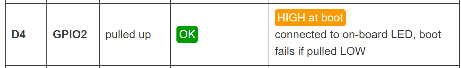
GPIO 2
I cannot use the serial pins because they are needed for programming the chip.
So I am left with GPIO 0 and 2..
Since GPIO 0 is hard coded by the chip to select between normal and flash programming modes I believe that my only remaining choice here is GPIO 2.
Is this correctly understood? Is GPIO 2 free for general use?
I plan on using a 10K pull-up on the pin with a small debounce capacitor to ground so the pin is high with the relay contact open. The relay shorts to ground when activated but only for a short time (some milliseconds). But it happens with longer times in between (minutes to hours).
When it does then the capacitor immediately discharges and there is the debounce on the pin.
So it is really not a relay but a reed switch operated by a moving magnet as described on this webpage: Raspberry Pi Pico Rain Gauge
I figured not everyone knows what a reed switch is so a relay contact would get the idea over...
Except I don't want to use a RaspberryPi because I just want it to send the rain data to my server.
No local display or other electronics needed, it will sit on top of the roof on my summer cottage inaccessible once installed.
So that should be possible for example using an ESP8266 type ESP-07s, which I have used before.
OTOH even that is too much so I am looking at using an ESP-01 instead.
What I am wondering is if the ESP-01 GPIO2 can be used or if there is some gotcha like GPIO2 is being reserved for something else as well.
So there is a contact closure on the reed switch for each tip of the rain collecting bucket.
The closure is caused by a magnet on the bucket passing over the reed switch when it tips and the duration of that closure is unknown by me but I would estimate it to be in the 10-100 ms range...
But the actual closure depends on the time it takes for the magnet to pass over the reed switch when the bucket tips over...
Simply the fact that it has closed, possibly also a running count of the number of tips since:
It was started
last midnight
the last hour
Here I don't really know the best approach, but maybe just send a timestamp when it is tipping and then let the MQTT subscriber read that and do whatever is needed.
The sensor itself does not need to manage these items.
The context was clear enough to set the scene for the question which was « can I use GPIO 2 on an ESP-01 to check the status of some possibly bouncy signal that I plan to filter using an RC circuit. »
The setup up checks the reason why the esp was awaken (wake-up from ISR or cold boot/reset). If you were awoken by the interrupt you connect to wifi, report the event and shutdown wifi
Then in all cases you setup GPIO2 as an external interrupt and go to deep sleep.
A clean front from the reed switch will wake up the ESP-01 regardless of whether it last a few ms or not.
(Probably the filter you use so that you don’t get any bouncing does not matter much because by the time you connect to wifi and send your MQTT message the bouncing will be done - so may be it’s not even needed).
The ESP-01 might not be the best choice those days - for about the same price and form factor I would look at an ESP32-C3 chip (like the XIAO) which is more « modern » than the outdated esp-01 firmware, sports more features and richer API and has a programming usb port to make it easy to use and will draw less current in deep sleep.
Thanks for your great info!
I will try with the ESP-01 first and look at the other chip later.
But I think deeps sleep might not cut it since the bucket will probably tip quite often if there is a rain storm and I don't want to miss them due to chip startup or similar items.
OTOH it could mean that I can use batteries instead of wiring 5V up to the device (I will put a 5->3.3V regulator on the ESP-01).
Needs to be checked as a later improvement maybe.
I was wondering if you can bring a wire over there at all. I envisioned more a battery powered self sufficient system with a small solar panel or something.
if you can power the device directly, then you'll have wires going to the roof and you could also consider actually bringing the signal indoor where the arduino would be more protected and easier to access.
if the Arduino does not need to sleep, then any of the "rain bucket" counting tutorial can help out for the basic code.
You'll have to test what happens to the interrupts when the arduino is busy in the MQTT transaction with an esp01
RX and TX are still GPIO (3, 1).
Keep the ESP01 removable for programming (as nec.)
You have to come up with a solid source of 3.3V
Part of a server-client scheme, it can read the reed and send that back upon client request
Exactly, this is what I realized when I had a bit more thought about it.
It seems like bringing the reed switch 2-wire cable indoors would make the whole thing simpler.
I am now on location and will check what is feasible, the project is in a fluid state right now...
In fact I tried the concept using a commercial sensor I bought on AliExpress and was delivered after about a month...
And I picked a RaspberryPi Zero-W instead since I could then use simple bash commands to create a test system.
It does work, but is not viable since I have now discovered that at the summer cottage I cannot get anything wired onto the roof...
So I need a self-powered system and that brings me back to the ESP-01 again...
So here I need some help in coding the ESP-01...
The reed switch in the sensor will be connected with a pull-up resistor of about 10K to 3V3 and will only consume power during the tip-over pulse. So that can be neglected.
What I need to do is figure out some sane strategy to minimize power consumption of the ESP-01 so batteries can be used...
Pulse
I have seen that the pulse generated by the reed switch at tip-over is roundabout 100 ms in length so the ESP-01 needs to be able to see that kind of pulse arriving. And there are minutes in between for a normal drizzle.
What could be the best strategy for this?
Messaging
I think the best way is to send an MQTT message on every pulse arrival, but that requires a WiFi connection, which is not needed during the pulse waiting period...
Can I fire up WiFi, connect to the broker, send the message and then shut down WiFi again in order to reduce continuous power drain?
If so how can it be done?
Timing
Yesterday we finally had a rain storm after a long time of drought and I managed to use the sensor and RPi-Zero to capture the first data.
During the 8 hours I measured there was 42 counts (about 11 mm of rainfall) and the time between tips turns out to be not less than in the minutes range, so the problem of pulse overlap seems to be a non-issue...
Given the above, what is your advice in order to make a battery powered ESP-01 based meter solution?
Can I configure the ESP-01 for deep sleep to wake up on the pulse input pin going low?
How long will it take an ESP-01 to start up, connect WiFi, send the data and then shut down?
I suppose you can connect the pulse to the RST pin. It going LOW will take the ESP out of deep-sleep.
Every time it starts up you can configure it to connect to WiFi and transmit that a pulse has been received.
Internal counting is actually not really required and not recommended, since the EEPROM is a simulated flash form that would wear out.
less than 10 seconds normally. One could consider adding another ESP to do the counting for you at a location where power is available so that you do not only depend on a remote storage of the information.
What is the power consumption of an ESP-01 with WiFi switched off and just a loop function to check the state of the input pin?
If the simple loop is just reading the state of the input pin I imagine it would not be very costly..
Then one could have a loop function that detects the change in input state and at that time fires up WiFi and sends an MQTT message about the state change and switches off WiFi again until the next trigger arrives.
Would this bring down current consumption to some low level compatible with battery powering?
It would still draw 15mA.
Deep sleep is available and you can wake up like @Deva_Rishi wrote in post 14.
Or simplify your life and buy $2 NodeMCU board.
So you mean that by connecting the reed switch to the RST input it will force a reset of the ESP and bring it out of deep sleep irrespective of the state of the deep sleep counter?
Then this would probably work for me:
The startup() code, where everything is then done, will do something like this:
(The ESP-01 will be in reset as long as the reed switch is active.)
Start WiFi and wait for it to connect
Initialize the MQTT system and connect to the broker
Compose and send the "rainpulse" message
Delay a bit to make sure the message is properly sent
Re-activate the Deep Sleep function with a VERY LONG timeout
Loop() is empty in this case.
This would not require me to modify the ESP-01 module, just hook it up normally and connect the reed switch between the RST input and ground.
One problem (not important):
The code will execute once when power is applied since there is no difference between this and the execution after the rain pulse has terminated. RST start in both cases.
But that is a 1-count offset only.
Yep that's the idea. The counter isn't available since that pin isn't exposed, but you don't need the counter (which would otherwise be connected to the RST pin and pull it low after an x amount of time)
yep.
good plan, you may even try to verify the reception by the MQTT broker, i don't know. never used that.
The timeout is rather irrelevant, since the timeout pin is not connected to RST so even if the timeout expires, still the ESp isn't woken up.
Yes, and with a pullup ! (most ESP-01 's have one on RST, but an extra 10K never goes astray)
yes. Also since it is battery powered you may want to check on the state of charge in some way.
Another point of concern may be the WiFi connection. It can happen that the ESP may not succeed in connecting, but in that case you may just do a soft restart of the ESP to let it try again. Probably best practice to make sure the client has fully stopped so the router won't get confused.
Thanks, that will be it then.
Previously I have built a number of temperature sensor devices to record temp/humid data in the attic of my home and then I have used devices like ESP-07s and ESP-12. But that required a lot of electronics handiwork to build on a vero board.
I also built 2 electricity meter devices using ESP-07s (no built-on antenna) for my home and summer cottage. For these I needed an external WiFi antenna because the meter is located in a metal box on the lot border. Hence need antenna for range reasons.
Now I am at the summer cottage and have all of my electronics gear back home, just a soldering iron here.
So I need a super simple solution using the ESP-01 I brought "just in case"...
I have an USB to Serial TTL adapter so I can program the ESP-01 and my laptop to do the software on. Feels like Robinson Crusoe...
I think this will be working, thanks for your confirmations and advice!