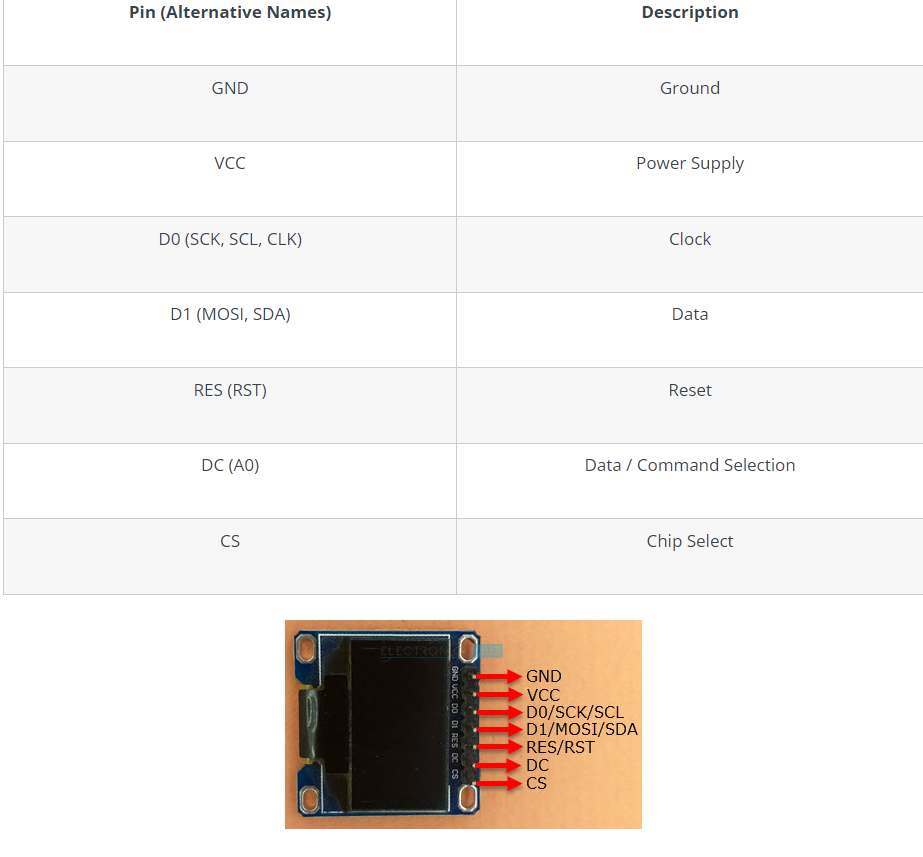
I have a project that need to use SIM Card module and also display module. I already implemented the SIM Card module using pin 16 and 17 for serial. Later I realized that I need pin 16 and 17 for connection with the display using SPI. I'm using 7 pin OLED SH1106, and it uses SPI for connection. I follow this for the wiring:
But at first I use pin 3 for DC and 1 for RES (serial 0) because I already used pin 16 and 17 for SIM Card module. The code run without issue, but no response from the display module.
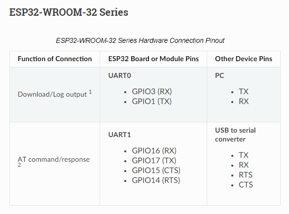
I did some research, and found that pin 1 and 3 should only be used for log :
What should I do to run the display module? Should it share the serial with SIM card module?
You should NOT use the IO-pins GPIO-1= Tx and GPIO-3=Rx that are used for the serial connection towards the computer at all.
You will be in trouble if you want to do a single serial print or if you want to upload a new code-version over serial if you connect something to IO-pins 1/3
You can re-map the SPI-interface to different Pins
this tutorial shows how to do that
SPI requires 5 IO-pins. A OLED SH1106-display is a rather small display.
Why don't you change to a I2C-version that needs only 2 io-pins?
Not only are the SPI pins free assignable, but so are the UART pins. a standard ESP32 has 3 UARTs and all can be assigned pins of your choosing.
Although it is not very practical, there is no real harm in using those pins as GPIO's if you observe their direction.
There are plenty of pins available so it shouldn't matter. In fact connecting something may cause it to malfunction simply because it is connected to the USB to TTL converter, even if that is a Serial device, so if you would want to use Serial0 to connect to another Serial device you should re-assign the pins.
Serial1 is by default connected to pins that are connected to the Flash, so also those should always be re-assigned. Serial2 is usable straight out of the box,
DC would be MISO, RES is reset and can be any GPIO pin that can be set to OUTPUT.
which article ?
i recommend this one
Not necessarily, DC seems different than MISO, still i think it is anyway using software SPI so it shouldn't really matter at all. Just pass the pins you want to use. You can also just first see if you get it working with what they suggest, and use the exact sketch, and simply use different pins for Serial2