First time connecting ESP32 Dev module to a RING LED
I verified the wires using wokwiki wokwiki
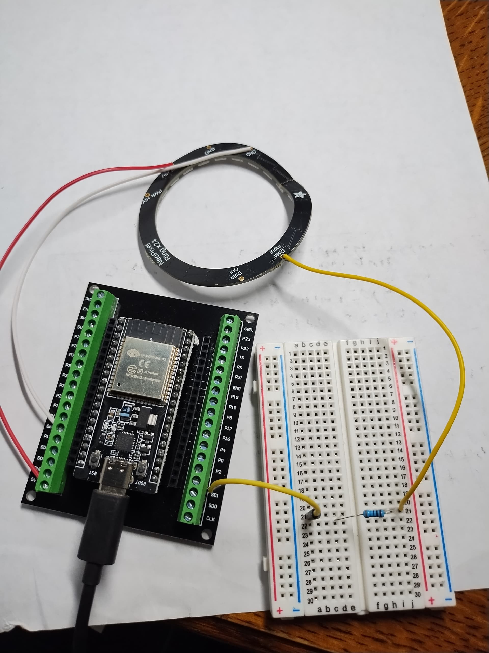
I connected GND, GPIO15, and +5v
But the Ring lights do not come on. no lights
The led strip arrived in rough shape
Did I hook it up wrong? Or should I return the LED strip?
Why does the ring have a extra GND and +5v?
Here is my code (using microPython neopixel library)
from machine import Pin
from neopixel import NeoPixel
from time import sleep

pixels = NeoPixel(Pin(15), 16)   #  Gpio  15 , 16 pixels.

print('test  pixels 0-2')

# test first 3 pixels.
pixels[0] = (255, 0, 0) # set to red, full brightness
pixels[1] = (0, 128, 0) # set to green, half brightness
pixels[2] = (0, 0, 64)  # set to blue, quarter brightness
The ESP32, in fact all ESP processors run at 3V3 so that means you are trying to power a 5V LED with only 3V3 signals.
You need some sort of level shifter to boost the 3V3 signal to 5V. The level shifters designed for I2C are not fast enough to take the required speed and work on the limit. I use an external logic chip to power all my 3V3 systems. this is the circuit I use :-
You say in the title ringx24 but in your program you define a 16 Neopixel ring.
I have the 16 Neopixel ring and I connect it GND - 3.3v - GPIO15 and it works ok, but a separate supply is much better especially if you want to light more than 3 leds.
Whichever you have there is a piece missing from the code, before the Neopixels will light you have to issue the write() instruction.
So lets modify your code with the write() instruction.
from machine import Pin
from neopixel import NeoPixel
from time import sleep

pixels = NeoPixel(Pin(15), 16)

print('test  pixels 0-2')

# test first 3 pixels.
pixels[0] = (255, 0, 0) # set to red, full brightness
pixels[1] = (0, 128, 0) # set to green, half brightness
pixels[2] = (0, 0, 64)  # set to blue, quarter brightness

pixels.write()
This link has a couple of really good Neopixel routines with instructables, check it out.
You should have been patient and returned the broken ring IMO.
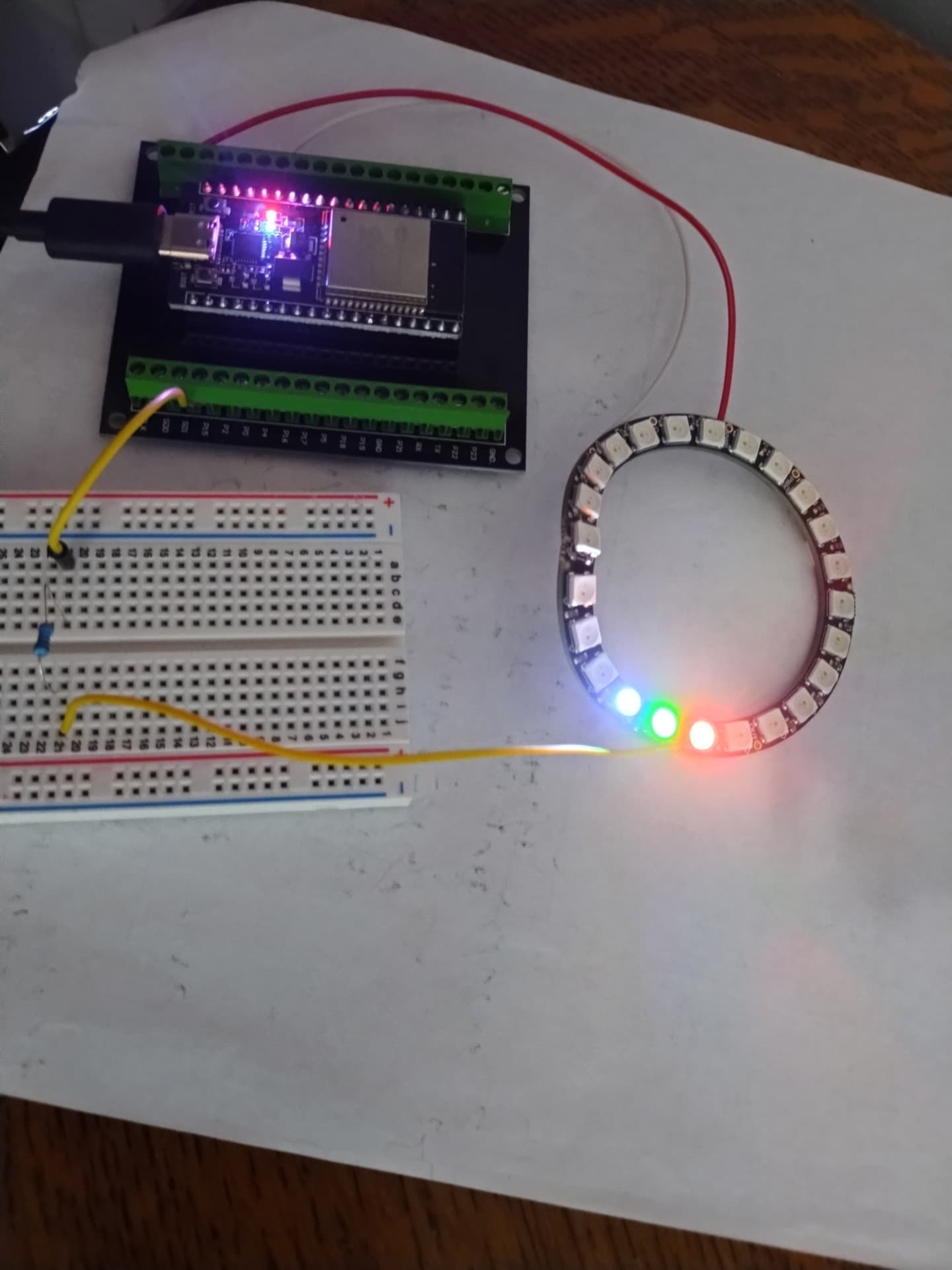
Grumpy Mike, I didn't change anything , and it started working! I am just using the resistor connected to gpio pin . The "level shifter" helps if big power draw , like more LED lights right?
Once the first led is lit then the signal is regenerated as a 5V signal by the next led. You must be on the edge of it working, so might not be reliable.
You also need a capacitor something like 100 to 1000uF at the start of each LED ring to smooth the voltage, this is especially true with a long chain of LEDs.
It is likely it didn't work before because you solderless bread board was not making good connections, they are notorious for that.
Also remember that an un lit LED takes about 1mA of current so with long chains this can be significant.
You had an other topic about that. Return that strip as was advised.
And yes, I understand that you're eager to continue with your project. It's the reason why I pay more by buying local from a small supplier; I will have a replacement within two or three days (and they come and collect).