How to connect wemos d1 r32 with CD74HC4067

Hi folks I have made following example.

With arduino Uno with a multiplexor that is working flawless

1

I am using following code

const int muxSIG = A0;
const int muxS0 = 8;
const int muxS1 = 9;
const int muxS2 = 10;
const int muxS3 = 11;
 
int SetMuxChannel(byte channel)
{
   digitalWrite(muxS0, bitRead(channel, 0));
   digitalWrite(muxS1, bitRead(channel, 1));
   digitalWrite(muxS2, bitRead(channel, 2));
   digitalWrite(muxS3, bitRead(channel, 3));
}
 
void setup()
{
   pinMode(muxSIG, OUTPUT);
   pinMode(muxS0, OUTPUT);
   pinMode(muxS1, OUTPUT);
   pinMode(muxS2, OUTPUT);
   pinMode(muxS3, OUTPUT);
   Serial.begin(9600);
   delay(1000);
}
 
void loop()
{
   for (byte i = 0; i < 16; i++)
   {
      Serial.println(i);
      SetMuxChannel(i);
      digitalWrite(muxSIG, HIGH);
      delay(200);
      digitalWrite(muxSIG, LOW);
      delay(200);
   }
}

The code loops every analog signal on the multiplexor and afterwards each light will blink.
¨

I want to have the same solution but instead with
wemos d1 r32

link to card below:

also I got following multiplexor

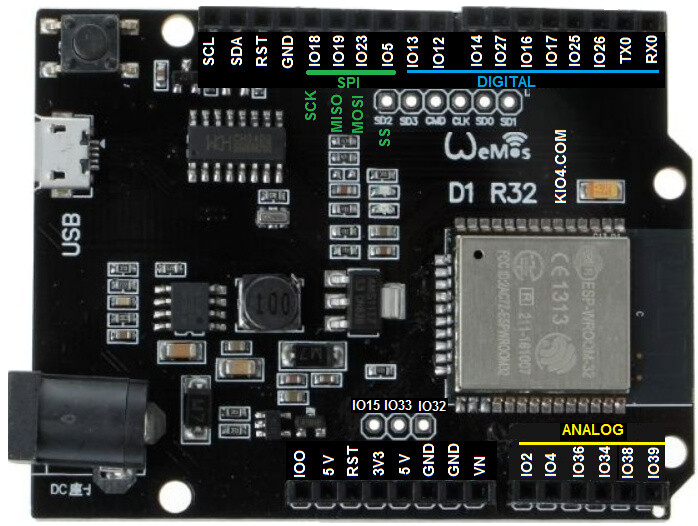
below is how I connected everything on the wemos d1 r32 card.

Here is the code

const int muxSIG = A0;
const int muxS0 = 8;
const int muxS1 = 9;
const int muxS2 = 10;
const int muxS3 = 11;
 
int SetMuxChannel(byte channel)
{
   digitalWrite(muxS0, bitRead(channel, 0));
   digitalWrite(muxS1, bitRead(channel, 1));
   digitalWrite(muxS2, bitRead(channel, 2));
   digitalWrite(muxS3, bitRead(channel, 3));
}
 
void setup()
{
   pinMode(muxSIG, OUTPUT);
   pinMode(muxS0, OUTPUT);
   pinMode(muxS1, OUTPUT);
   pinMode(muxS2, OUTPUT);
   pinMode(muxS3, OUTPUT);
   Serial.begin(9600);
   delay(1000);
}
 
void loop()
{
   for (byte i = 0; i < 16; i++)
   {
      Serial.println(i);
      SetMuxChannel(i);
      digitalWrite(muxSIG, HIGH);
      delay(200);
      digitalWrite(muxSIG, LOW);
      delay(200);
   }
}

I am not sure of which pins I should rewrite the code I was looking on the pin layout for Wemos d1 R32 but still little confused of what is the right way of do this

Following images below might be helpful

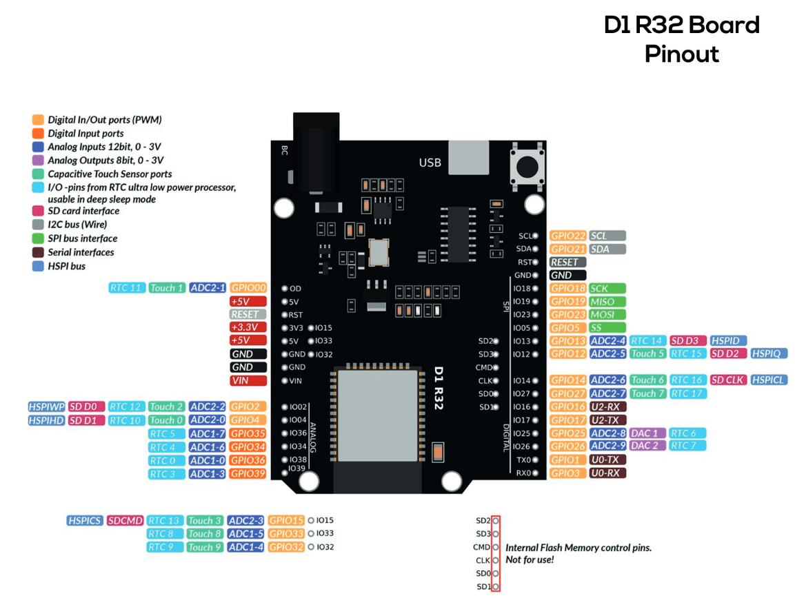
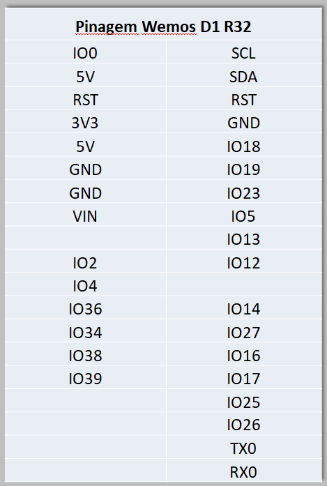
according to below image my connection are wrong but I am not sure

Please help me out how to do this

Thank you in advance

My best tip for successfully building prototypes:

  1. Buy several large breadboards and clip them together.
  2. Buy an MCU board that is compatible with breadboards, that plugs directly into a Breadboard.
  3. Buy other components that will be needed in a form that is also breadboard compatible, that plugs directly into breadboard.
  4. Use solid core cable to hook up all components, cut to length and laid flat and neatly to the breadboard.

My best tip for unsuccessful prototypes:

  1. buy only one small breadboard
  2. buy an MCU with a shield form-factor, but don't buy any kind of shield to use with it
  3. Buy other components that are breadboard compatible, but don't plug them into the breadboard. Instead, solder breadboard-incompatible headers to them to make them breadboard incompatible.
  4. Wire everything up in a massive rat's nest of flying wires.
  5. Scratch your head as you wonder why it doesn't work and why you can't figure out which is all those tangled wires could be faulty or connected to the wrong pin.
1 Like

Have you been spying on me? :expressionless:

a7

Just change these pin numbers to the ones you are using on the D1.

You are powering the mux from 5V, that will mean 5V levels on the I/O pins, which can damage the ESP I/O pins (they are 3.3V level).

1 Like

Seems like its not working no result unfortunately.

My last atempt was

const int muxSIG = A0;
const int muxS0 = 026;
const int muxS1 = 025;
const int muxS2 = 017;
const int muxS3 = 016;

What information was your attempt based on?

By the way, why did you put zeroes in front of the numbers? That will make them base 8, for example 026 is 2x8+6 = 22 decimal.

However, apart from that, your diagram shows the mux connected to 12,13,5,23 not 26,25,17,16.

What is going on over there? :slight_smile:

Many thanks for corrections though still not working

now I have

Many thanks for help though now in Serial Monitor based on below code:

const int muxSIG = A0;
const int muxS0 = 12;
const int muxS1 = 13;
const int muxS2 = 5;
const int muxS3 = 23;
 
int SetMuxChannel(byte channel)
{
   digitalWrite(muxS0, bitRead(channel, 0));
   digitalWrite(muxS1, bitRead(channel, 1));
   digitalWrite(muxS2, bitRead(channel, 2));
   digitalWrite(muxS3, bitRead(channel, 3));
}
 
void setup()
{
   pinMode(muxSIG, OUTPUT);
   pinMode(muxS0, OUTPUT);
   pinMode(muxS1, OUTPUT);
   pinMode(muxS2, OUTPUT);
   pinMode(muxS3, OUTPUT);
   Serial.begin(9600);
   delay(1000);
}
 
void loop()
{
   for (byte i = 0; i < 16; i++)
   {
      Serial.println(i);
      SetMuxChannel(i);
      digitalWrite(muxSIG, HIGH);
      delay(200);
      digitalWrite(muxSIG, LOW);
      delay(200);
   }
}```

I get in the Serial Monitor: Selected Both NL & CR , 115200 baud

�E (10109)��E (11120)��E (12131)��E (13142)��E (14153)��E (15164)��E (16175)��E (17186)��E (18197)��E (19208)��E (20219)��E (21230)��E (22241)��E (23252)��E (24263)��E (25274)��E (26285)��E (27296)��E (28307)��E (29318)��E (30329)��E (31340)��E (32351)��E (33362)��E (34373)��E (35384)��E (36395)��E (37406)��E (38417)��E (39428)��E (40439)��E (41450)��E (42461)��E (43472)��E (44483)��E (45494)��E (46505)��E (47516)��E (48527)��E (49538)��E (50549)��E (51560)��E (52571)��E (53582)��E (54593)��E (55604)��E (56615)��E (57626)��E (58637)��E (59648)��E (60659)��E (61670)��E (62681)��E (63692)��E (64703)��E (65714)��f�x~xf���xf�x�~�xx���xf�x�`����xf�x���f���x

Ln 37, Col 2

UTF-8

ESP32 Dev Module

on COM5

2


Since I using Serial.begin(9600) I tested to select New line and 9600 instead:
then I get:

�E (10109)��E (11120)��E (12131)��E (13142)��E (14153)��E (15164)��E (16175)��E (17186)��E (18197)��E (19208)��E (20219)��E (21230)��E (22241)��E (23252)��E (24263)��E (25274)��E (26285)��E (27296)��E (28307)��E (29318)��E (30329)��E (31340)��E (32351)��E (33362)��E (34373)��E (35384)��E (36395)��E (37406)��E (38417)��E (39428)��E (40439)��E (41450)��E (42461)��E (43472)��E (44483)��E (45494)��E (46505)��E (47516)��E (48527)��E (49538)��E (50549)��E (51560)��E (52571)��E (53582)��E (54593)��E (55604)��E (56615)��E (57626)��E (58637)��E (59648)��E (60659)��E (61670)��E (62681)��E (63692)��E (64703)��E (65714)��f�x~xf���xf�x�~�xx���xf�x�`����xf�x���f���xE (156704�E (157715�E (158726�E (159737�E (160748�E (161759�E (162770�E (163781�E (164792�E (165803�E (166814�E (167825�E (168836�E (169847�E (170858�E (171869�E (172880�E (173891�E (174902�E (175913�E (176924�E (177935

Ln 37, Col 2

UTF-8

ESP32 Dev Module

on COM5

2


Many thanks again @aarg

I get in following error

gpio gpio can only be used as input mode

The ESP processors are fussy about which pins you use for I/O. Some of them have special functions. You need to consult a reference guide for the specific ESP board/processor that you have, to determine which pins are safe to use for that.

This topic was automatically closed 180 days after the last reply. New replies are no longer allowed.