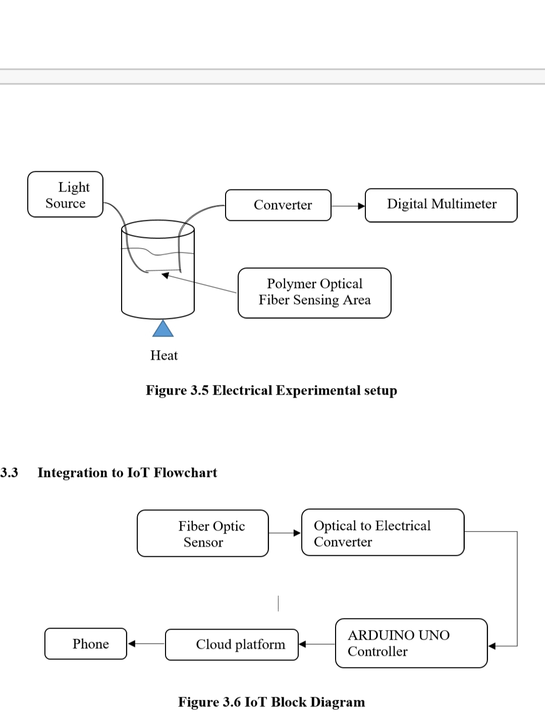
I've recently built temperature monitoring (30degree-80degree) using plastic fiber-optic (pof ) sensors with integration to iot.
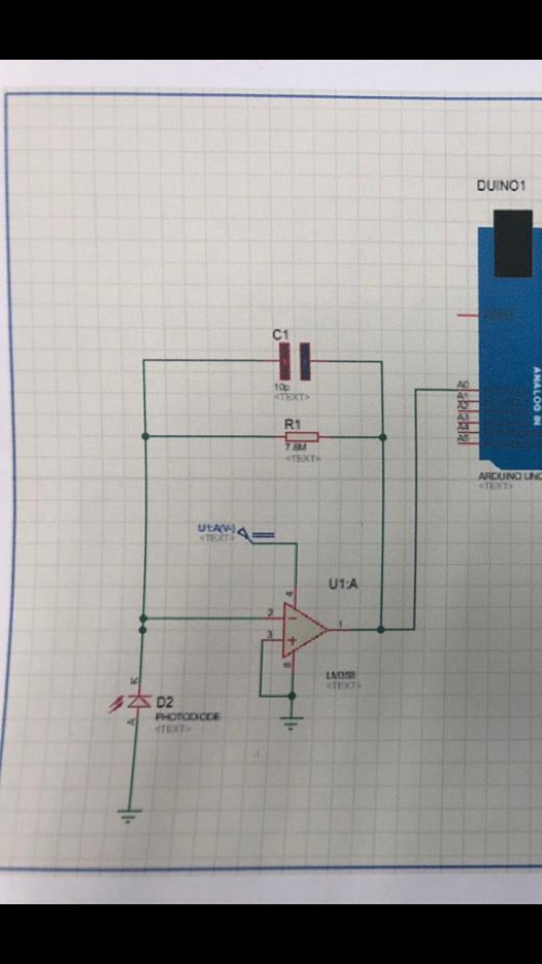
my project need me to built optical receiver circuit for detect optic fiber, and then convert to electrical signal for IoT to show output voltage from photodiode on the phone(blynk app)
my equipment use,
polymer optical fiber (POF) cladding at center
photodiode:IF -D91
op amp LM358p to amplify the signal
light source wavelength: 650nm
I want to read the values I get from receiver circuit into a computer via an Arduino uno R3.
when I'm measuring the light with this photodiode IF D91 and giving the Light source 650nm on the other end, the voltage fluctuations as measured by a multi-meter on the photodiode are linear, but rather small as the fiber is heated from 30degree to 80 degree. the voltage hovers around, 0.50V to 0.47V.
but after i connect to transimpedance amplifier to increase the voltage( C=10p, R=7.8M) , the voltage only reach about 3.7-3.6V
What I am worried about is losing resolution when doing A/D with the Arduino. If my voltage fluctuations are on the order of 10mV, won't the Arduino's 10-bit A/D quantize the hell out of it, How can I stretch out that range between 0.5 -0.47V to cover the full range, from 0V to 5V so that I can take advantage of the full range of the Arduino A/D?
I feel like this has got to be a common operation in electronics, but I've never studied it formally, so a lot of things are lost on me.
also here is my coding for the output voltage on arduino uno:
// read the raw data coming in on analog pin 0:
  int lightLevel = analogRead(analogPin);
  // Convert the raw data value (0 - 1023) to voltage (0.0V - 5.0V):
  float voltage = lightLevel * (5.0 / 1024.0);
  // write the voltage value to the serial monitor:
  Serial.println(voltage);
i hope you guys can help me, thanks in advance.