How to control motor speed with potentiometer

Not the most original question but nonetheless, I am new to C++ but I wanted to try to control the speed of DC motor with a potentiometer(below should be an image of the circuitry). I have also attached the code. The problem I am facing is that, whenever the potentiometer is at one extreme end, the rpm of the motor is 0, then whenever I turn the knob slightly from that end, the rpm goes from 0 gradually to 5555. I am trying to learn how to control dc motors with sensors, such as potentiometers, ultrasonic, pressure etc. so that is the main inspiration here. I do not understand where I have went wrong with the code, so could I have some guidance here please? And also any tips for the future, in case I make any similar mistakes.

int potin;
int pot;

void setup()
{
  pinMode(A0, INPUT);
  pinMode(11, OUTPUT);
}

void loop()
{
  pot = analogRead(A0);
  potin = map(pot, 0, 1023, 0 , 255);
  digitalWrite(11, potin);
}

There are very very few motors that can be powered by an Arduino output. You absolutely need a driver for the motor and an external power supply capable of providing the motor stall current. If you are lucky the Arduino has not been damaged.

Also the lack of a flyback diode is risking damage to the Arduino pin.

Is the motor to rotate in one direction or must it be reversible?

Oops

Your sketch is slightly corrected. Upload it and observe the behavior of the motor; it should be better.

byte potin;
int pot;

void setup()
{
  Serial.begin(9600);
}

void loop()
{
  pot = analogRead(A0);
  potin = map(pot, 0, 1023, 0 , 255);
  analogWrite(11, potin);
  delay(1000);
}

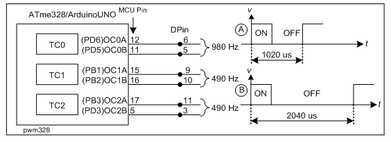
pwm328
Figure-1: PWM pins of UNO board, which can be driven by analogWrite() function

void setup()
{}

void loop()
{
  analogWrite(11, analogRead(A0) / 4);
  delay(1000);
}
1 Like

Yeah! You raised this issue (/4) that day; but, I miserably missed to answer.

This is the first time I am seeing an empty setup(){} function in an Arduino sketch though empty loop(){} function is common.

I see. A side question, is an esc(electronic speed controller) a type of motor driver? And an external power supply cable such as a LiPo battery or 9v battery(for arduino tinkercad cases). The arduino hasn't been damaged, as this is only virtually simulated.
The motor is to rotate in one direction.

yes my bad, I had originally thought as I was converting analog values to digital I would have to digitalWrite rather analogWrite

Okay thank you, the motor behaves accordingly now. I do wonder why the max rpm is 5555, is that due to the power supply of the motor? Considering it is being solely powered by the arduino. If I were to power it with an external 9V battery, would the rpm increase?

What was the reason for dividing the analogRead value by 4?

Because the analogue to digital converter is ten bit, but the PWM is eight bit.

If it had been an accurate simulation, it wouldn't have worked at all.

I gathered, largely due to motors not being powered by an arduino output, any other reason?

Ask the author of the simulator.

Yes. Usually uses a servo type signal for control, not analogWrite() type PWM.

That depends on the rated voltage and stall current of the motor. For a 3V motor a single LIPO cell (3.7V nominal) would be OK. 9V smoke alarm batteries are best left for smoke alarms. They do not have the current capacity for a motor.

If it works at all with real hardware, I expect it will not work for long and will most likely end with a damaged Arduino.

Then a simple MOSFET driver will work.

The lack of a flyback diode (D1 in the above schematic) will result in a high voltage being fed to the output pin when the current to the motor is stopped which will kill the pin at least.

1. There are two arguments in the analogWrite(arg1, arg2); function. The first argument (arg1) refers to one of the PWM pins (6, 5, 9, 0, 11, 3) as indicated in Fig-1 of post #5.

2. The 2nd argument (arg2) refers to the 8-bit unsigned value (0 to 255 in decimal base = 0x00 - 0xFF in hex base) which determines the duty cycle (ON-time) of the PWM signal.

3. You want to control the duty cycle taking value form A0-channel of the ADC in the following way:

unsigned int adcValue = ananlogRead(A0);

4. The value of adcValue is 16-bit (upper 6-bit always 0s and lower 10-bit comes from ADC); whreas, the agr2 of ananlogWrite() feuntion is 8-bit. Therefore, we have to compress the 16-bit (max: 1023) value to 8-bit (max: 255). This compression is done using the following function:

byte arg2 = map(adcValue, 0, 1023, 0, 255);

5. Now, the codes are:

unsigned int adcValue = ananlogRead(A0);
byte dutyCycle = map(adcValue, 0, 1023, 0, 255);
ananlogWrite(11, dutyCycle);

6. The above three lines can be written by the following single line code called embedded/nested form:

ananlogWrite(11, map(analogRead(A0), 0, 1023, 0, 255));

7. As 255 is almost = 1/4th of 1023 (= 255.75), the code of Step-6 can be written
as (@anon73444976):

analogWrite(11, ananlogRead(A0)/4);
1 Like

Will the spike of the generated high voltage kill the digital pin of the MCU or the transistor Q1? The Q1 will be subjected to the stress of the high voltage?

I meant that if the motor were connected directly to an Arduino pin, no driver or diode.

But, in either case, direct drive with a pin or with a transistor the diode is necessary to protect the pin or the transistor.

Correct.

Ohh I see, thank you! I understand. It’s a very clever shortcut