Hi,
Im with the starter kit lesson 9 motorized pinwheel.
How can i use a potentiometer to control the speed of the motor ?
Chapter suggest hooking up a potentiometer to an analog input and use that to PMW the pin that controls de transistor, but
if speed can be controled by voltage that the motor receives, i think it makes no sense to use pitentiometer on transistor other to switch on/off, am i wrong ?
I think may i need to connect potentiometer to the battery ?
How can i use the pot to control the speed?
With a microcontroller everything is done this way
The code reads input values from switches/sensors etc
The code determines what to do
The code drives output devices.
So your first steps are getting the input side of things working - for instance
printing meaningful values out on Serial to show you've captured the input
values/states correctly.
Then you test the output side of things to make sure you can control the outputs
as desired.
Then you write the "business logic" as it were that reads the inputs and current
state and determines what outputs are desired - this plugs everything together.
Here you need to figure out reading from the potentiometer into a variable,
then you figure out controlling the motor from a control value in a variable,
then you plug the two sides together - the business logic is probably a single
call to map().
Go here and read, particularly #6. - Scotty
Hi markt, i been developing software for a lot of years, so please leave the logic outside.
What my question is , that seems you not expressed well or you dont know, is
How to control the speed of the motor in lesson 9 of starter kit by using a potentiometer ?
Where i put the pot., in between the battery and the motor ? or in between the power of the board and the input of the board ? in last, what command fir programming ? if first case then do i need no code ?
I don't believe you have been developing software for many years, because you seem way too retarded.
MarkT's advice is exactly correct.
You connect your potentiometer to the analog input of the arduino, and read the voltage it produces, which will proportional to the position that you have turned the potentiometer knob to.
You then calculate a speed reference number based on this analog voltage input.
You then use the speed reference number to control the duty cycle of a PWM signal, which is output to whatever kind of motor drive circuitry you are using. Simple.
You cannot connect the potentiometer directly to the motor, for anything but the smallest and weakest motors. The current requirement of any usable motor, is more than the current which a normal potentiometer is capable of carrying without damage. Unless you have the sort of potentiometer used to control 1920's technology trains and trams, which I doubt.
How can i use a potentiometer to control the speed of the motor ?
I don't have access to your kit info, but I would think you would map the 0 to 1023 pot output to 0 to 255 to generate a 0 to 255 PWM value to drive your motor driver.
Zoomkat. that seems to be correct.
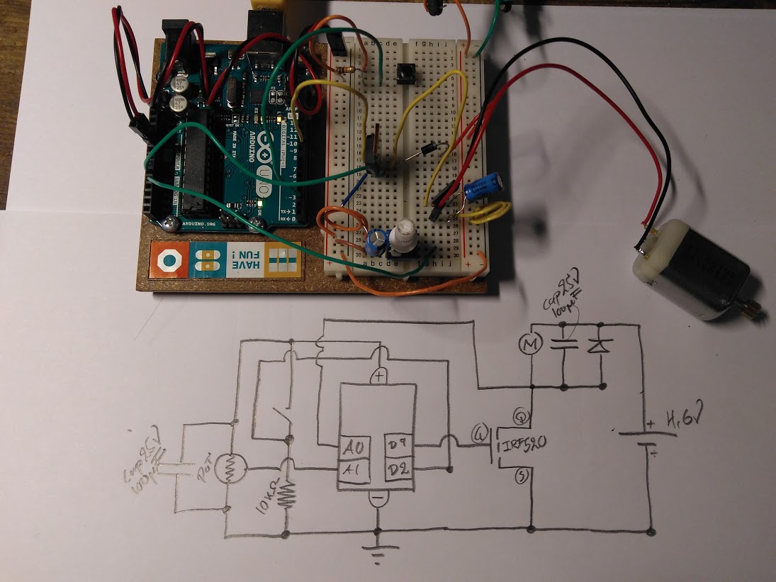
The Pot is wired directly onto + rail and ground rail ( not onto the Motor circuit itself). Potentiometer is wired like pictured on page 64 in the startkit book, and the Pot sensor wire to A1. the A1 is programmed as an "analogRead". The serial monitor can then display the values on A1, from 0 - 1023. The Program directs the A1 10bit analog signal to D9, digitalWrite, that feeds the MOSFET gate port.
I then saw that the motor started between A1 values 0-255, then stopped, on values above 255, it stared again, and then stopped on 512, then started again , toward 1023, then stopped on the max level ! Therefore I mapped the A1, AnalogRead value onto 0 - 255, so the motor didnt stop, as I cranked the pot.
// Assigment 09
// Motor control using Pot meter and PWM . page 98 Starter kit book . Arduino - UNO .

const int D2=2; // Manual button on the board must be pressed for action
const int D9=9;

void setup (){

//Serial monitor
Serial.begin (1200);

// declare pinmodes
pinMode (A0,INPUT);    // Reads the 10 bit 0-1023 value behind the Drain on the mosfet
pinMode (A1,INPUT);    // Reads the 10 bit 0-1023 value on the Pot meter . 2^10 = 1024 .
pinMode (D2,INPUT);    // Reads the binary 0 or 1 value (0 or 5V) on the manual switch
pinMode (D9,OUTPUT);   // Writes the binary 0 or 1 value (0 or 5V) to Transistor Gate
} //end SETUP

void loop (){

float readdrain = analogRead (A0);
float DC_supply = 4.6; //measure the Volts on your own DC supply to get correct readings
float volt = (readdrain / 1023.0) * DC_supply; // formula on page 49 in the starter kit book.
float voltdrop = DC_supply-volt;
float ohm_circuit = 65.7; // 4.6V / 0.07A = 65.7 ohm
float ampere = voltdrop / ohm_circuit;

/*When the switch is open, there is no Amperes on the circuit.
But there is still a Voltage differance between the terminals.
The "tap" wire or sensor wire (A0), measure full blast of 1023, even with no Amperes on the circuit.
I therefore figured the Volt Drop had to be used to calculate the Amperes ...

The Diode prevents current from going in the wrong direction .
the Capacitor discharges when the circuit Voltage is lower than the Voltage charged up in the cap, smoothing ripples  .*/

int readpot = analogRead (A1);
int potangle = map (readpot,0,1023,0,255); // 1023 is translated to 0 - 255 on the serial monitor.
int switch1 = digitalRead (D2);
if (switch1 == 1){
analogWrite (D9,potangle);
} // end IF
else
{analogWrite (D9,0);
} // end ELSE

Serial.print ("Analog Value: ");
Serial.print (readdrain);
Serial.print ("\tCircuit Volt: ");
Serial.print (volt);
Serial.print ("\tVolt Drop: ");
Serial.print (voltdrop);
Serial.print ("\t\t");
Serial.print ("Ampere Circuit: ");
Serial.print (ampere);
Serial.print ("\t");
Serial.print (switch1);
Serial.print ("\t");
Serial.println (potangle);
}//end LOOP
For the initial inquirery of Gosbrut. I was also surprised that I could level up and down the GATE voltage and the motor responded gradually increasing in speed. I thought the Transistor were like ON or OFF. And it is more or less, the motor changes speed slightly .
I also found out that the 10 bit analogRead reads 0 at 0 Volts and 1023 at about 4.6V. So having a 9V DC supply as said in the instruction is out of measure fro the UNO board ...
( I accidentally applied 9V * 3A onto the transistor and had the Diode backwards, the MOSFET was smokin , hahaha. but it survived . )
radarblue, your post was incredibly helpful! a lot of what you had in your code was a bit beyond my entry level programming but I was able to pick it apart enough to generate my own code
const int switchPin = 2;
const int motorPin = 9;
int const potPin = A0;
int potOutput;
int potVal;
int switchState = 0;

void setup() {
  pinMode(motorPin, OUTPUT);
  pinMode(switchPin, INPUT);
  Serial.begin(9600);
}


void loop() {
  potVal = analogRead(potPin);
  Serial.print("potVal:  ");
  Serial.print(potVal);
  potOutput = map(potVal, 0, 1023, 0, 255);
  Serial.print(", voltage: ");
  Serial.println(potOutput);


  switchState = digitalRead(switchPin);


  if (switchState == HIGH) {
     analogWrite(motorPin,potOutput);
  }
  else {
    digitalWrite(motorPin, LOW);
  }

}
I did get the circuit to work and the pot controls the motor speed as well as post the voltage values. My code is a lot more simplistic but I'm not attempting to read other values from around the circuit. Your example is definitely something I can learn from. Well done and thanks!
I realize this is well after the fact for this forum subject but, for future programmers, the programming right above my comment by vampyrewolf is spot on. I am able to change the speed of the motor by using this potentiometer. The A0 input seems to be more responsive on the pot input, not sure why. Maybe it's just my board. But, this string in the loop works great.