Almost: the diode shouldn't be between the 47K and pin 1 of the opto but between pin 1 & pin 2 of the opto, the ring (the cathode) being connected to pin 1.
One other thing: PC817 is unidirectional (only one LED) and is therefore a better choice than the bidirectional Vishay H11AA1 although Fig 1 page 3 shows that 0.7V should not allow the LED to conduct current.
The OP's three-phase is a DELTA arrangement with no neutral.
But the one with two leds like in H11AA1 means I have an led lit up in every half and that causes two rising edges for both positive going and negative going and I only desire the positive going.Because one led will be reverse biased and the other forward biased and when there is a change in wave polarity the reverse is true the other led that was reversed now becomes forward and the other reverse and that gives me two rising edges for both negative and positive and I require only positive going.
Hi, @derrick-pro
Can you tell us what your project actually is?
Not what you are trying to do.
If all you need to do is detect phase rotation, you don't need a neutral connectetion.
If you are try to detect zero crossing of each phase to use in a phase load control, then you still do not need neutral if your load is DELTA.
Can you please tell us your electronics, programming, arduino, hardware experience?
Thanks.. Tom.... 


Am trying to use this to detect phase squence
You don't need neutral, not even an earth.
This and all handheld sequence meters do not use neutral.
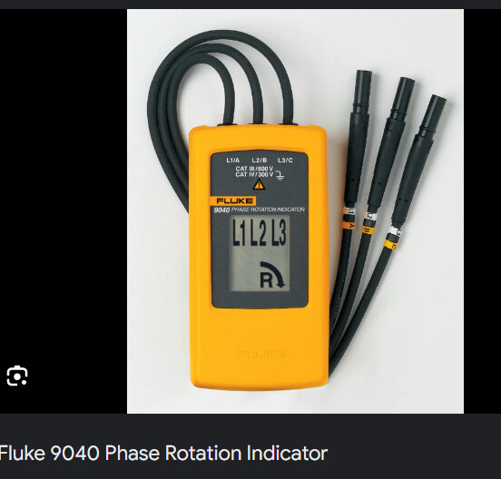
Only three connections.
This might help, reasearch
https://www.researchgate.net/figure/Schematic-Diagram-of-3-phase-Sequence-Detector_fig2_301478340
From this site;

Tom....
Thanks TomGeorge let me head there and read.
I suggest that for a single phase that you use a circuit like the following, instead of your circuit from post #36:

Note, that the diode has been repositioned. This gives 2 advantages over your circuit:
-
The maximum reverse voltage of the LED in the opto-isolator is only 6V.
In your circuit the reverse voltage (220V x √2 = 311V) is shared between the 1N4007 diode and the LED in the opto-isolator. There is no guarantee that all the voltage is across the diode, and that less than 6V is across the LED.
With the circuit as I have drawn it the maximum reverse voltage across the LED is the forward voltage of the 1N4007 diode, so only around 0.7V. -
With the circuit as I have shown it, it draws the same current in the reverse direction as it does in the forwards direction.
This means that you can combine three of these circuits to form a balanced 3 phase load:

I believe that this is what you are looking for.
The 1N4007 eliminates one of the detections because it becomes conductive (=0.7V) when current flows from its anode to its cathode so the opto only has 0.7V between pin 2&1 which is (should be) less than its min Forward voltage: no detection for this half of the sinewave. My point was: 0.7V is not far from the ~0.8V temperature sensitive threshold shown fig.1 page 3 that I mentioned post #61 so a unidirectional opto is safer.
BTW, if the only thing you want is phase sequence, you don't need a virtual ground and
the drawing post #52 should do but with the diode between pin 1&2 (antiparallel).
Virtual ground is necessary if you need zero crossing detection too.
The drawing from @JohnLincoln is the right one for zero crossing detection.
Etienne_74 was trying to explain that circuit to you whilst I was drawing the schematics.
@derrick-pro does not have a neutral connection.
Tom....
He doesn't need a neutral connection because the 3 phases are 120° apart and all 3 legs have the same impedance.
A.sin(ωt) + B.sin(ωt + 120°) + C.sin(ωt + 240°) = 0 whatever ω and t as long as A = B = C (identical impedances)
Another angel,thanks johnKincoin, am looking for answers like this and this is beautifully shown with diagram.Hope this works well with star, how about in Delta where there is no neutral?
Yes, you can use it in delta, but you will need to use higher value resistors as the voltage is higher.
The voltage in delta is 220V x √3 = 381V.
Also help draw the diagram to use on delta. Am happy people are coming up to my rescue am really happy thanks everyone who is working to get this done.
Yes zero crossing positive going is what I need.

Thank you so much johnLincoln, for the diagrams (I would love to know the software you use for the diagrams) thank you Etienne_74, kmin, TomGeorge and the rest thank you so so much for working hard and seeing that this get up to this point, I now have two diagram to play with at least I have were to start from, am very happy nice people for all this please keep the good heart 
I think it's Proteus from Labcenter Electronics, one of the best out there...
See post #77 by @JohnLincoln