Hi guys, I want to make a LM358 circuit that can generate a 50 Hz sine wave output with 5V output. Can anyone help me with a schematic of this circuit ?
thanks.
Hi guys, I want to make a LM358 circuit that can generate a 50 Hz sine wave output with 5V output. Can anyone help me with a schematic of this circuit ?
thanks.
Hi,
Did you Google;
lm358 sine wave oscillator circuit
Tom... ![]()
![]()
![]()
![]()
Yes, but I'm not sure if those circuits have a frequency of 50 Hz
You can do the math to adjust it to yu our needs.
I'd also suggest using Ltspice to stimulate it. Takes some getting used to, but it's really handy.
Hi,
Can you please tell us your electronics, programming, arduino, hardware experience?
You will have to do some maths..
Thanks.. Tom... ![]()
![]()
![]()
![]()
I have little information in the field of electronics and circuit design. But I have enough skills in Arduino
Well, this is all about electronics and not about Arduino, so you're going to learn ![]()
But I do not have enough time for learning electronics right now ![]()
Well, if you happen to live in a country where the grid frequency is 50Hz, you could always simply use a transformer. Or does ot have to be battery operated?
This circuit must be battery operated
And again, more to the point, why do you want 50 Hz, how accurate do you want the frequency and why must it be a sine wave - which if you answer all, will tell us how accurate or inaccurate you need it to be and whether or which one of the two principal sine wave oscillator circuits is required? ![]()
That is going to hurt!
Relevant questions from @Paul_B. Those really should be answered first.
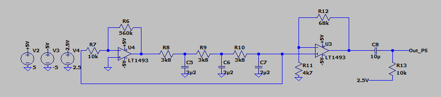
But playing ahead for a bit, something like this could work:
I want to compare the frequency value of the op-amp with the ZMPT101B module to find the phase shift so the frequency must be 50Hz.
Hi,
Why?
For what project?
Depending when you turn the op-amp on will determine what the phase difference is.
I think a complete explanation of your project would be good.
Thanks.. Tom... ![]()
![]()
![]()
![]()
I need a sine wave as a reference to be able to find difference between the other phases.
How many phases?
Is this for 3 phase power measurement.
If so why not use one of the existing phases a reference, it will be at exactly the same frequency which your have specified in your request.
Tom... ![]()
![]()
![]()
![]()
3 phase.
Because the other phases are not close to each other, so I need a sine wave simulator as a reference.
Hi,
What is your project?
Thanks.. Tom... ![]()
![]()
![]()
![]()