How to execute loops faster?

Hey Forum,
I've been working a bit on making a relatively small timer using an ATTINY85 and only a few I/O pins. I'm using the 74HC164 shift register to shift in the segments to the displays. When I run the code via the ATMEGA328, it runs great. Segments turned on are bright on, and segments that are off are 90% off or close to. My issue comes when I'm now running the code on the ATTINY because it takes longer to shift the segments in. And as this occurs 'live' you see them shift in, but really quickly. Then I have it pause afterwards for 10ms to display the finalised digit. Then because it takes longer to shift them in, it will create a ghosting affect and it's very hard to distinguish those on and off because it probably is taking 10ms to shift them all in.

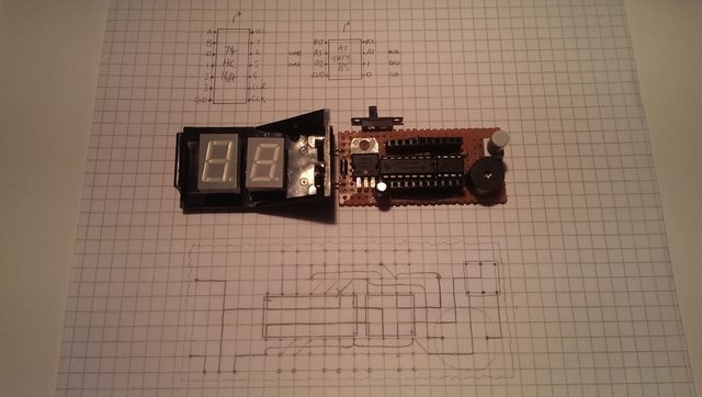
It doesn't look as bad in real life, the ghosted segments are 20-50% full brighness, but it's still not too appealing. In this photo, the number that should be displayed is 01.

Ok, my question is, how do we make this process run faster like it does on the ATMEGA?
I've looked at a few options:
-Directly controlling the pins instead of the longer instruction digitalWrite() - but I can't seem to understand how
http://www.paleotechnologist.net/?p=1808
-Purpose built libraries to execute faster - but the library would take my over my 8k of space on the ATTINY85
http://forum.arduino.cc/index.php/topic,46896.0.html
-Port manipulation of the pins, but would this work on my ATTINY85? and if so how?

Code I am running to load the segments in:

...
//<<Declaration of segments and numbers>>
bool bitmap[22][8]= 
{
//{h,c,d,e,g,f,a,b}, KEY
  {0,1,1,1,0,1,1,1}, //0                a
  {0,1,0,0,0,0,0,1}, //1               ---
  {0,0,1,1,1,0,1,1}, //2            f |   | b
  {0,1,1,0,1,0,1,1}, //3               -g-
  {0,1,0,0,1,1,0,1}, //4            e |   | c
  {0,1,1,0,1,1,1,0}, //5               --- .h
  {0,1,1,1,1,1,1,0}, //6                d
  {0,1,0,0,0,0,1,1}, //7
  {0,1,1,1,1,1,1,1}, //8
  {0,1,1,0,1,1,1,1}  //9
};
...

...
//<<Shifting the code to the shift 74HC164>>
void displayDigit(int digit)
{
  for(int pos = 0; pos < 8; pos++)
  {
    digitalWrite(CLK, LOW);
    if(bitmap[digit][pos] == trigger) digitalWrite(DATA, HIGH);
    else digitalWrite(DATA, LOW);
    digitalWrite(CLK, HIGH);
  }
  delay(10);
}
...

Is the ATtiny85 configured to run at 1 MHz or 8 MHz?

It' running at 1MHz, but that'd be a great increase and help to make it 8x faster if it wasn't.

The 164 doesn't have a latch pin, so you see all the grubby details of the shift. Use a chip like the 74xx595, that does have a latch pin so it doesn't matter how slow the shift is.


Rob

Hi Rob,
I do have other shift registers, but I don't have a spare PIN on my microcontroller.
The ATTINY85 has 5 GPIO pins, and I'm using all 5.

  1. Data for shift register
  2. Clock for shift register
  3. Common anode for first display
  4. Common cathode for second display
  5. Dual purpose pin for both a buzzer and a button
    With this microcontroller, there are very tight restrictions. But I like it because it's a challenge and also, keeping everything to a small footprint.

Any ideas on how the code can be written to run faster?

The first step is to reconfigure the processor to run at 8 MHz. Have you done that?

Hmmm, a tiny85 eh?, that does restrict things a tad.

What CR said, then start using direct port manipulation instead of things like digitalWrite().

If you add a single external gate you can probably use the two digit selects to latch the shift register...oh hang on, one display is CA and the other CC, what's the idea with that?

EDIT: How about using the USI, that will shift out at several MHz speed.


Rob

Gratuitous self advertising alert :wink:

You really do need to get rid of that crumby shift register. Get yourself a '595, or better still, one of my constant current sink 16-bit shift register modules:

http://www.ebay.co.uk/itm/191009620140

Direct drive of all 16 segments of a dual digit common-anode display, with no resistors needed. Uses the same protocol as the '5975, so has the nice handy latch pin for clean updates. Update it at whatever speed you like and no ghosting at all - ever.

What's a 575??

If you search for "Changing the ATtiny85 clock speed", you'll get a ton of hits. For example:

MarkT:
What's a 575??

Why do I keep calling them 575's? they're 595's! :roll_eyes:

And that advert must have worked, I just sold out :wink: But the bare chips are easy enough to come by if you want to make your own...

STP16CP05

use
uint8_t pos iso int pos

do direct port manipulation iso digitalWrite()

  if(bitmap[digit][pos] == trigger) digitalWrite(DATA, HIGH);
    else digitalWrite(DATA, LOW);

can be
   digitalWrite(DATA, bitmap[digit][pos]);
as HIGH = 1 and LOW = 0?

Bah, sorry for the extremely late replies guys. I didn't get any emails to say I had replies after I turned off for the day and I placed the project on hold while I worked on a car alarm project. (Which is having it's own problems, and I just posted another topic today.

I haven't been replying, but I have brought pictures as a reward for your extended wait.

This is the total idea and how I normally do my layout designs. I always with every project try to make them as small as possible. So I have the displays stacked on top of the DIP packages. It also saves me having to route them all. Apologies that my components aren't official symbols, like the resistors. I just have them curve up and not on the lines so I know they're above the board. Also the connections between the 2 segments aren't displayed, but they're the ones at the far top and bottom. I just have jumper wires between them you can see below.

This is the front design. I already had most of it planned before I created this post. But I soldered it all together soon after. I wasn't really considering another shift register. Especially not being able to spare another pin.

This is how the back works. It's sometimes difficult to get the pads to bridge, but it's certainly not impossible. Obviously the switch was not included in the original design, as well as the diode, but I'll add them in as I realise I need them.

And this is how it looks when it's all soldered together without the displays blocking everything. Also, the switch is a NO/NC switch. So the pin I'm using it on is OUTPUT when using the beeper with the NC of the switch. And when using it as an INPUT with the switch, the beeper acts as a pull down resistor because it ran about 5K Ohms.

Graynomad:
If you add a single external gate you can probably use the two digit selects to latch the shift register...oh hang on, one display is CA and the other CC, what's the idea with that?

Hahaha, yes it's not how I'd do it. But I got them for free from an electronic bits bundle and they were the only I had on hand. I hated to see them go to waste, so I thought I'd make a project out of them. If you look in the pictures above, that's why they're oddly sized and most likely different manufacturers.

So one of digit select pins goes high impedance INPUT whenever I need to send signals to the other one. But I think I'd still need 2 because the other digit will display the opposite of the digit displayed.

Graynomad:
What CR said, then start using direct port manipulation instead of things like digitalWrite().

robtillaart:
use
uint8_t pos iso int posjavascript:void(0);
do direct port manipulation iso digitalWrite()
as HIGH = 1 and LOW = 0?

I've looked into the direct port manipulation. I just wasn't sure if it was the same when used on the ATTINY85. I do like this option though.

econjack:
If you search for "Changing the ATtiny85 clock speed", you'll get a ton of hits. For example:
http://ediy.com.my/index.php/tutorials/item/49-change-the-tiny-arduino-between-1mhz-and-8mhz

It's already selected as 8MHz in the Arduino Menu... Unless there's another way to do it. But with simple math I'm guessing that my shifting code only runs at 8MHz instead of 16MHz as it does with the ATMEGA328. So the delay is there for twice as long shifting in the bits?
I realised this when uploading it as 1MHz and obviously it running 8x slower than I expected.

I guess I could always select it at 20MHz in the menu, I'd just need to alter the delays(); in my code to run 25% faster.
This would work right?

alxndr:
I guess I could always select it at 20MHz in the menu...

Do you have a crystal + capacitors or a resonator connected to the processor? If "no" then 20 MHz is not a good choice.

alxndr:
It's already selected as 8MHz in the Arduino Menu...

And? Did you remember to execute Tools / Burn Bootloader to actually change the fuses?