I am using an Arduino UNO to control a trim system on my jet ski. The OEM system uses a shaft with a magnet to move along a rail that has reed switches mounted on the sides. Each reed switch has a different resistor hooked up in series with it. Up and down buttons are used to control a motor to move the shaft in or out by changing polarity (same as a window motor and window switch in car). Each reed switch outputs a different ohm reading between 20-140 ohms to know the position of the shaft. The ends of travel both have a reed switch hooked up to a 167 ohm resistor. These act as limit switches. When these reed switches are closed, I need the Arduino to prevent the shaft from moving any further in that direction. The motor can only spin in the opposite direction. For example, if the shaft is moving up and reaches the max travel, the shaft will not continue to move even if the operator continues to hit the up button. However, if the operator hits the down button, the shaft should be able to move down.
I need help figuring out a way for the Arduino to know which limit switch is closed so that the Arduino can prevent movement in one direction depending on which limit switch is closed. Both limits have the same resistance and it is not possible to change these resistor values as the control board is coated in resin to make it waterproof.
I was thinking I could store the previous position of the shaft before it hits the limit switch and then the Arduino will know whether it is hitting the max or min limit switch. However, I have the jet ski powering the Arduino so it will only be on when the jet ski is on. So when the jet ski is shut off, the previous position will be lost. Any help would be greatly appreciated!
As position is given by those reed switches, you can just read it when you power up the thing, same accounts for limit switches if it's pushed against one.
If in between switches, wait until the user presses the up/down button to get to the nearest reed (or limit) switch. As the limit switches are at the ends of the travel, you know which reed was the latest to be triggered: it's the one next to the limit switch.
wvmarle:
Connect the limit switches to individual inputs.
All the reed switches are hooked up in parallel with each other. Only two wires are what I have to read off of. If you connect a ohm meter between the two wires, the resistance between the two wires changes based off of which reed switch is closed. So I cannot have different inputs for each switch.
wvmarle:
If in between switches, wait until the user presses the up/down button to get to the nearest reed (or limit) switch. As the limit switches are at the ends of the travel, you know which reed was the latest to be triggered: it's the one next to the limit switch.
This is what I was thinking. However, when the arduino is powered off and back on and the shaft is sitting at a limit, the arduino will not know which limit it is at.
Read the analog/resistor value ans use a series of if statements to get the position
See Sparkfun and look at the code for the Weather Shield - with a bit of luck part of it is below
//Read the wind direction sensor, return heading in degrees
int get_wind_direction()
{
    unsigned int adc;

    adc = analogRead(WDIR); // get the current reading from the sensor

    // The following table is ADC readings for the wind direction sensor output, sorted from low to high.
    // Each threshold is the midpoint between adjacent headings. The output is degrees for that ADC reading.
    // Note that these are not in compass degree order! See Weather Meters datasheet for more information.

    if (adc < 380) return (113);
    if (adc < 393) return (68);
    if (adc < 414) return (90);
    if (adc < 456) return (158);
    if (adc < 508) return (135);
    if (adc < 551) return (203);
    if (adc < 615) return (180);
    if (adc < 680) return (23);
    if (adc < 746) return (45);
    if (adc < 801) return (248);
    if (adc < 833) return (225);
    if (adc < 878) return (338);
    if (adc < 913) return (0);
    if (adc < 940) return (293);
    if (adc < 967) return (315);
    if (adc < 990) return (270);
    return (-1); // error, disconnected?
}
Appears more likely that , if connected the way you describe, the resistance you describe is a voltage divider.
Then, when any particular reed closes, a different voltage is transmitted to the control.
bluejets:
Appears more likely that , if connected the way you describe, the resistance you describe is a voltage divider.
Then, when any particular reed closes, a different voltage is transmitted to the control.
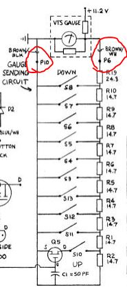
I attached a picture of the schematic of the circuit that is being used by the system. The two circled wires in red are what I am able to read off of.
That's different from how you described it.This way every single switch (including the limit switches UP and DOWN) has a unique resistance. You should be able to read the voltage on P6 with an analog input - likely you need an additional voltage divider to bring it down to a proper value, ideally to a value of 0-1V so you can read it with the internal reference.
Now the second problem is that this voltage is not going to be stable: it will vary with the battery voltage of the snow machine itself. So you will also have to read this voltage (on a separate analog input), or you may end up in between two switches with your calculated resistance reading...
wvmarle:
That's different from how you described it.This way every single switch (including the limit switches UP and DOWN) has a unique resistance. You should be able to read the voltage on P6 with an analog input - likely you need an additional voltage divider to bring it down to a proper value, ideally to a value of 0-1V so you can read it with the internal reference.
Now the second problem is that this voltage is not going to be stable: it will vary with the battery voltage of the snow machine itself. So you will also have to read this voltage (on a separate analog input), or you may end up in between two switches with your calculated resistance reading...
So this circuit that I have above is not hooked up to any power. So I am not able to read any voltage. I can only read a resistance between the two wires.
Then you will need to apply a voltage.
The Arduino cannot measure resistance.
What is the value of the first resistor on the voltmeter or did you not intend to use this part?
The arrangement you show above is a variable shunt value however, the low value might well need a rethink for direct input to arduino.
This is basically a variable resistor, with the value depending on which reed switch is closed (you should be able to read this resistance with your multimeter). If those numbers are the resistance in Ohm, that is a very low resistance giving pretty high current when connected straight to the 5V.
Then there's this mysterious Q5, a MOSFET that can block the UP signal entirely. The schematic suggests there's a third connection to this device, where this MOSFET is connected. Unless you switch this on the reed S10 is not going to do anything and you can not detect its signal.
I only have access to wires P10 and P6 as shown in the schematic I had posted. I connected a multimeter between these two wires and slide the shaft along the reed switches. The Ohm values I read are below when moving the shaft from up to down.
168.7 ohm
25.5 ohm
39.9 ohm
55.1 ohm
68.4 ohm
82.8 ohm
97.1 ohm
111.4 ohm
125.8 ohm
140.1ohm
168.7 ohm
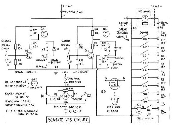
The 168.7 ohm is the limits of travel. Below is the whole schematic if you wanted to see. This is how the systems is supposed to work. However, it was destroyed with water and doesn't work with power hooked to it. Just shorts out.
zack19:
I only have access to wires P10 and P6 as shown in the schematic I had posted. I connected a multimeter between these two wires and slide the shaft along the reed switches. The Ohm values I read are below when moving the shaft from up to down.
Looking at the schematic that should be down to up, not up to down(!).
What I see with these numbers and the schematic:
168.7 ohm - no reed triggered at all (out of range - you measure the total of all resistors present).
25.5 ohm - S8 (24.3 Ohm), this is the DOWN position.
39.9 ohm - S7 (24.3+14.7 = 39 Ohm)
55.1 ohm - S6 (24.3+14.7+14.7 = 53.7 Ohm)
68.4 ohm - S5 (...+14.7 = 68.4 Ohm)
82.8 ohm - S4 (...+14.7 = 83.1 Ohm)
97.1 ohm - S3 (...+14.7 = 97.8 Ohm)
111.4 ohm - S13 (...+14.7 = 112.5 Ohm)
125.8 ohm - S12 (...+14.7 = 127.2 Ohm)
140.1ohm - S11 (...+14.7 = 141.9 Ohm)
168.7 ohm - again no reed triggered (...+14.7+14.7 = 171.3 Ohm)
The UP switch S10 is indeed not seen at all, without having that MOSFET Q5 switched on or otherwise bridged.
I expect you will see the 168.7 Ohm reading when you're in between two measurement points as well. The "limits of travel" appear to be out of your actual limits (physical limits of the levers or whatever it's connected to, I'm not familiar with snowmobiles as such).
wvmarle:
Looking at the schematic that should be down to up, not up to down(!).
That's correct. I was moving down to up. Wrote it backwards. And whenever the magnet is not present or exceeds the limits, you are correct, the ohm reading is 168.7.
wvmarle:
I expect you will see the 168.7 Ohm reading when you're in between two measurement points as well.
When moving the shaft back and forth I never experienced a point where I was between two readings.
wvmarle:
The "limits of travel" appear to be out of your actual limits (physical limits of the levers or whatever it's connected to, I'm not familiar with snowmobiles as such).
I need to have limits to prevent the motor from over extending the trim which the shaft is connected to. I do not want it to reach the physical limits of the mechanism. The limits that are safe for travel are between the S8 and S10 switches. It is alright that the S10 switch will not be used. I do not need it to extend that far up.
So if I supply a voltage at P10 wire, and read the voltage at the P6 wire with the Arduino, I will know the position of the shaft correct? I will store the previous position of the shaft and if I reach a voltage produced by the 168.7 ohm, I will know which limit I am at as well based off of the previous position. This limit will be stored in EEPROM so if the Arduino is shut off, it will still know which limit its at. Does that all make sense? You have been very helpful, Thanks!
To read the resistance: you need to create a resistor divider. So 5V - external resistor - P6 and P10 - ground. Your reading is then from P6.
A 220Ω pull-up would give an analog reading range of about 100-450 with steps of some 65 ADC points between two setpoints, while limiting the current through the resistors to no more than about 21 mA. That sounds very reasonable to me.
For the programming: it's great that you don't see the full resistance in between, that means there's an overlap where two reed switches are activated at the same time (the one with higher resistance you simply don't see yet). As as result, a reading of 169Ω (or more) is out of bounds. You should stop the movement the moment you find either the low (25Ω) or high (140Ω) points. This prevents the system to over-extend either way, and the moment you switch on the Arduino you know exactly where you are. For added safety, consider a too low reading also as a fault.
There are two situations where you can get to the 169Ω point.
When moving (past a low or high point, or intermittently). If stopping the moment you find the high or low points, this should never happen, yet it won't hurt to account for it. This should be considered a fault condition, most likely a wire broke. Stop moving until the reading becomes in range again.
When starting up with the sensor placed out of the normal range. Again this should never happen and should be treated as a fault condition, as you don't know on which side of the range you are, or whether the sensor is operating properly to begin with.
That is a great idea. I could just set the limits on the 24.3ohm and 141.9ohm readings. That way I don't have to worry about the out of bounds reading and knowing position. I will set a 169 ohm reading as a fault.
wvmarle:
To read the resistance: you need to create a resistor divider. So 5V - external resistor - P6 and P10 - ground. Your reading is then from P6.
A 220Ω pull-up would give an analog reading range of about 100-450 with steps of some 65 ADC points between two setpoints, while limiting the current through the resistors to no more than about 21 mA. That sounds very reasonable to me.
I am a little confused with this set up. I understand the resistor divider, (just like a voltage divider correct?) So I am reading the voltage at the P6 wire. Would the 220ohm pull up resistor be my external resistor? I don't see how I would be getting a range of 100-450 doing a quick calculation with 220ohm as my external resistor and a resistance reading between my P6 and P10 wires.
Now at the lowest end you have 24.3Ω, and a simple calculation gives 0.5V on that resistor, that's an ADC reading of about 100. On the other end of the scale, you're at 2.2V, which is about 450 on the ADC.
Note: in your programming, don't bother calculating resistances or so, you don't care about the resistance, just what setting you have, so you can use the ADC readings directly. Considering tolerances in the resistors you have to do a simple calibration where you measure the readings for the different set points, then use those as mid points in determining where you are. E.g. you have readings at 100 for the first, 150 for the second, 200 for the third, 250 for the fourth, etc; then you look for 75-124 for the first, 125-174 for the second, etc:
if (reading < 75) { // fault! Upper disconnected, or shorted out.
}
else if (reading < 125) { // first
}
else if (reading < 175) { // second
}
[etc]