I am new to arduino world and have got my self "2.2 Serial SPI TFT Color LCD Module" LINK
After reciving the product I discoverd that the display works on 3.3v Logic and that my arduino (arduino mega2560) ouput pins are 5v.
I have been trying to find solution on google, but without luck.
My problem is that I don't have level shifters (I orderd few but its going to take 2 weeks until it arrives).
From my understanding I can make my own level shifter using Resistors to make the screen work. But how I don't know. I found few small pictures, not clear enough to see what happends.
One of the store comments says: "...Use 47K resistors for connections to all the ports (MISO, MOSI, RST, CS, CD) because the board is 3.3V and Arduino is 5V by default. Connect Vcc and LED to the 3.3V connector...", I tried this but did not work for me. Some also say use 4.7k resistor istead of 47k.
So, thats why i decided to ask help from you guys. Could someone please help me out.
"How to get 2.2 TFT work on Arduino mega 2560 without level shifter(s)" ?
You can also now use the 2.2" QVGA TFT SPI display based on the ILI9341 driver. To use this display load the Adatfruit_IL9341_AS and Adafruit_GFX_AS libraries. Connect the display to the UNO as follows:

UNO +5V to display pin 1 (VCC) and pin 8 (LED)
UNO 0V (GND) to display pin 2 (GND)
UNO digital pin 7 through a 1K2 resistor to display pin 4 (RESET), add a 1K8 resistor from display pin 4 to GND
UNO digital pin 8 through a 1K2 resistor to display pin 5 (DC/RS), add a 1K8 resistor from display pin 5 to GND
UNO digital pin 9 through a 1K2 resistor to display pin 3 (CS), add a 1K8 resistor from display pin 3 to GND
UNO digital pin 11 through a 1K2 resistor to display pin 6 (SDI/MOSI), add a 1K8 resistor from display pin 6 to GND
UNO digital pin 13 through a 1K2 resistor to display pin 7 (SCK), add a 1K8 resistor from display pin 7 to GND
It is important to include the 1K8 resistors to GND with this 2.2" display as otherwise it will not work. The 1K2 and 1K8 resistors are a "potential divider", acting as a logic level shifter so that the logic level at the display is reduced from 5V to around 3V. Pin 9 of the display does not need to be connected up.
But I don't have the 1k2 and 1k8 resistors. The lowest I got is 1k resistor. Any other resistors that may work ? Or do i need to wait up my order of level shifters :(?
ArduinoStarter2015:
But I don't have the 1k2 and 1k8 resistors. The lowest I got is 1k resistor. Any other resistors that may work ? Or do i need to wait up my order of level shifters :(?
Other resistors will work, those happened to be the ones I had in the box. Keep the ratio about the same. If you have lots of 1K resistors then replace 1K2 with 1K and 1K8 with two 1K in series!
The picture is not what you want, MISO is the Master In Slave Out signal that is driven from the display. The circuit is odd too, a 1K in series will be OK as the display will output a 3V3 logic signal. MISO is only needed if you wire up the SD Card or want to read pixel data back from the display.
rowboteer:
Other resistors will work, those happened to be the ones I had in the box. Keep the ratio about the same. If you have lots of 1K resistors then replace 1K2 with 1K and 1K8 with two 1K in series!
The picture is not what you want, MISO is the Master In Slave Out signal that is driven from the display. The circuit is odd too, a 1K in series will be OK as the display will output a 3V3 logic signal. MISO is only needed if you wire up the SD Card or want to read pixel data back from the display.
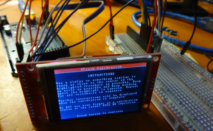
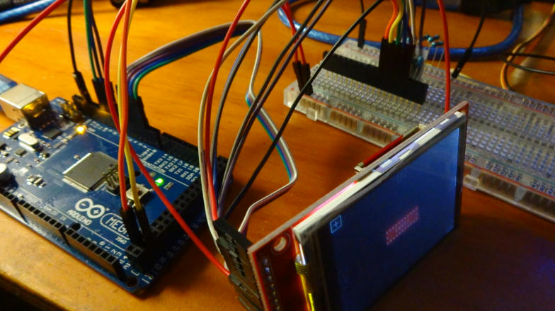
It works! It works on 5v aswel as on 3.3v. Is it safer to leave the vcc and led on 3.3v? Or does it not matter?
The display has a 5V to 3.3V regulator (reference designator U1 on the back) so it is safe to power from 5V.
The backlight signal line "LED" is connected to Q1 on the board so you can switch on/off with a digital pin to save power or to PWM the line to have an adjustable brightness.
The display has a 5V to 3.3V regulator (reference designator U1 on the back) so it is safe to power from 5V.
The backlight signal line "LED" is connected to Q1 on the board so you can switch on/off with a digital pin to save power or to PWM the line to have an adjustable brightness.
I recently got this 2.2 display. Couldn't find any schematics for it, this post is super helpful. Rowboteer would you happen to know what J1 jumper is for?
Also would you you happen to know if LED needs an external resistor?
Here's pick of back from mine...
EDIT: I realized that U3 is footprint for Flash chip! How cool is that! It even has it's own CS line, so you can have both SD card and Flash!
bratan:
Rowboteer would you happen to know what J1 jumper is for?
Also would you you happen to know if LED needs an external resistor?
J1 is to bypass the 5V to 3.3V regulator, so it could be powered from 3.3V directly.
Transistor Q1 switches the LED on/off and has a base resistor R4 so the transistor can be driven directly from a logic line connected to the LED pin. The LED control pin connects to the transistor switch and hence does not directly power the LEDs, so you could PWM this pin to control the brightness.


