I need to get an accurate, stable voltage reading across two points of the order of microvolts to be stored as a value and do some calculations... Is there any way I could achieve it precisely? Has anyone had the experience of making one? What should I do?
That's going to be difficult....
You'll need a high-gain low-noise amplifier. Not an easy thing to build. (Probably some kind of "instrumentation amplifier".)
Thermal noise may be an issue even before worrying about amplifier noise and electrical noise pick-up. Thermal noise is random so if you are measuring DC it can probably be (mostly) filtered-out and it also depends on temperature and resistance and a lower resistance/impedance will have less noise.
I have a meter at work with 5 digits past the decimal point which means it has 10uV of resolution but I don't know about the accuracy.
24-bit ADC would give you microvolt resolution. Check Adafruit and such.
Yes, it can be done. No, it's definitely not trivial.
- Zeroth, define your accuracy. This will determine the amount of hair-pulling involved.
- First, assume that breadboards are out of the question completely. Don't even think of it!
- Second, find an accurate, temperature-stable reference voltage.
- High-resolution ADCs are a dime a dozen, but read the accuracy and drift specs carefully.
- Avoid the usual hobbyist spots. Cheap parts have too many compromises.
- Try to do it using through-hole components because the only way it has a snowball's chance of working is with a solid ground plane with interconnections as short as possible. PTH components are relatively easy to assemble "dead-bug" style on a solid copper-clad sheet.
- Leakage is everywhere. Clean everything scrupulously.
I used to collect rules-of-thumb and application notes on precision low-level measurements. Sadly, I don't know where to find most of them online. This is the only one I could remember well enough for google to find.
Jim Williams and Bob Pease articles and application notes are gold here. https://www.analog.com/media/en/technical-documentation/application-notes/an86f.pdf
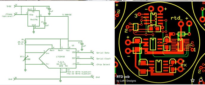
Here is a successful use of a 24-bit ADC I did a few decades ago along with a picture of the PCB art. I have no idea where the files are.
Stable accurate uV measurement out of hobby grade equipment. Looking forward to see this work.
Use industrial grade components and just read and display the answer with hobby equipment. ![]()
I remember reading Bob Pease articles in some electronics magazine.
The OP also needs to identify who will calibrate his hand made device and how often!
@ARYN
The more information you can give about what you are measuring, the more advice you will get. For example, what voltage levels, how much accuracy (%, ppm, etc) required, temperature over which you will operate, etc.
In addition posted you want to consider low thermal test leads getting your signal from where it's at to your measurement plane. You are not going to do any of this with hobby grade off the boat components. I have been to this rodeo and the price of admission is expensive, very expensive.
Ron
Without more input from OP, it’s not clear if we’re talking about microvolt resolution or actually a few microvolts of signal. Two very different design cases.
Have to agree with that. ![]()
Doesn't really say much. Order of microvolts across two points? In my day, well a few days ago measurements like this involved a Fluke 720A Kelvin Varley Divider, A Fluke 845 AB Null Meter (running on the battery) and a Fluke 732 DC Reference Standard. That was just the start. Then a few sets of Fluke low thermal test leads. While this mountain of precision by todays standards may be archaic it was the standards equipment used. Pretty expensive mountain when you want to resolve micro-volts. Then store the data for whatever reasons.
So the thread starter can come back and explain in detail what they wish to do. Till then we kick back with chips. ![]()
Ron
I notice the OP did NOT say the readings had to be repeatable.
Typically you use a precision preamplifier near your source, really close. The signal from the preamplifier then goes to an ADC. Try that everything has a stable temperature, without gradients, and is very well shielded from any kind of noise. Check the classical 'Keithley Low Level Measurements Handbook'.
It's operated in the room temp.
"VanderPauw Method" to find resistivity of thin film.
Why do you need microvolts resolution?
What is your sensor?
Can you please tell us your electronics, programming, arduino, hardware experience?
PLEASE a proper description of your application would help.
Thanks.. Tom.. ![]()
![]()
![]()
![]()
PS. If you are using a thermocouple, there are many modules that can interface one to the Arduino environment.
As I have replied to you earlier, this project is to measure the resistance of thin film precisely and accurately. You can google "Vander Pauw Method to find resistivity" to know more about the project. Currently I am using a 24 bit ADC and some noise reduction filters to measure the voltage drop between 2 points on the thin film. But even then, the readings are neither stable nor accurate.
You may need to put the measurement assembly inside a shielded container.
Do you have a scope to see what power noise you have?
Tom.. ![]()
![]()
![]()
![]()
