How to get working a capacitative humidity sensor

Hello

My friend borrowed me a capacitative humidity sensor.
It is only the component, it is not a plug & play module.

I am used to work with 3 pin sensors, relays, etc. But I don't know how to make this working fine.

One problem is that We don't know which model is. But I've googled and maybe I found it. My friend says it's the HC-201 (http://www.epluse.com/fileadmin/data/product/hc201/datasheet_HC201.pdf).

I think it is the Honeywell HCH-1000 series.

I've followed various topics, and tried to investigate by myself.

Those links are more useful:

http://forum.arduino.cc/index.php?topic=55812.15
http://starter-kit.nettigo.eu/2010/humidity-sensor/

Sorry, my english is bad. And also I am a newbie in electronics.

Thanks in advance.

P.d. I would know how to definately connect it and how to read values more or less acurrately.

If you are new to electronics, perhaps you better buy another humidity sensor.

The capacitance humidity sensors needs a pulse or frequency to measure the capacitance.
This shows a sketch Using an HS1101 humidity sensor - #6 by wildbill - Sensors - Arduino Forum and a schematic.
I hope you can read that schematic, it used 1M resistor parallel to the sensor and a 220 ohm to an Arduino pin.

Hello,

I've been reading for a week about the HCH-1000 humidity sensor by capacitance, and some others which are similar. Also I've been reading code, testing and trying to develop an accurate way of reading the RH %.

Well, so I found those links (which I post for your interest and your utility):

http://starter-kit.nettigo.eu/2010/humidity-sensor/

http://forum.arduino.cc/index.php?topic=64849.0
http://arduino.cc/forum/index.php/topic,55812.0.html

  • I'm missing some, but I think it's enough to make your own idea. There's a lot in the forum.

So my problem is that after a week and lot of tests, I've not found the way of getting it to work synchronized with my Termo-hygro-meter of ~10 euros.

First of all, I want to know if it's possible to make it work accurately (+- 2%), or just think it's working well. Because at the momment, when my termo-hygro-meter marks 33%, my sensor + code says: 39%. And when it's 41% it says 39%.... I am getting a bit crazy, and I think it's problem of my circuit.

So, if you have read my first link, you can know which is my circuit. The cable is not longer enough to loss data,
and I've been trying to get the MIN (0%) and MAX (100%) values for the Analogue Output. But, I can't leave it as done, because it's obvious that it isn't.

or I just can use an interrupt timer2 (or someone available), for doing the trick, or...

I ask you because I have no much idea, and because the first link, says you can do both ways... but the result is obviously a fail.

I tried to put into the 0 and 100 % following the oven trick with towel paper, but my termo-hygro-meter said 29% as lowest value, so I did this trick, which maybe is the problem:

if at 41% is X value
and if at 29% is Y value
then "I don't need 0 and 100 %", because:
X - Y = Z
and
41 % - 29 % = 12%
so, Z / 12 % = for example 30.5 values every 1% (very very low accuracy).
then minimum value (0%) should be: Y - 29 % * 30.5 = MIN
and maximum value (100%) should be: MIN + (100% * 30.5)

So I've got 1713 as MIN and 4763 as MAX.

But working really bad.

My code is this:

#define CHARGE_PIN 13
#define DISCHARGE_PIN 11
#define VOLTAGE_CHECK_PIN A1
// Scaling definitions
// Value for 0% humidity
#define HUMIDITY_0 1713
// Value for 100% humidity
#define HUMIDITY_100 4763

// 1 - Callibration mode
// 0 - Measurement mode
#define CALIBRATION 0

int counter = 0;

unsigned long charge()
{
  // Setting pins in charging mode
  pinMode(DISCHARGE_PIN, INPUT);
  unsigned long begin_time = micros(); // Loading the initial time
  pinMode(CHARGE_PIN, OUTPUT);
  digitalWrite(CHARGE_PIN, HIGH);
  // Waiting for the capacitor to reach 63,2% of supply voltage
  while (analogRead(VOLTAGE_CHECK_PIN) < 648);
  unsigned long end_time = micros(); // Loading the final time
  return end_time - begin_time; // Calculating the charging time
}


void discharge()
{
  // Setting pins in discharging mode
  pinMode(CHARGE_PIN, INPUT);
  digitalWrite(CHARGE_PIN, LOW);
  pinMode(DISCHARGE_PIN, OUTPUT);
  digitalWrite(DISCHARGE_PIN, LOW);
  // Waiting for the capacitor to reach 0V
  while (analogRead(VOLTAGE_CHECK_PIN) > 0);
}


unsigned int get_humidity() {

  unsigned long int humidity = 0;
  unsigned int counter = 0;
  while (counter < 300)
  {
    humidity += get_humidity0();
    counter++;
  }
  humidity /= 300;
  
  return humidity;
}

unsigned int get_humidity0()
{
  discharge(); // Discharging
  unsigned long charge_time = charge(); // Charging with time measuring
  // Scaling
  unsigned int humidity = map(charge_time, HUMIDITY_0, HUMIDITY_100, 0, 100);
  // Callibration mode (1) or measurement mode (0)
  if (CALIBRATION == 1)
    return charge_time;
  else
    return humidity;
}


void setup()
{
  Serial.begin(9600);
}

void loop()
{
  unsigned int humidity = get_humidity();
  float temp = get_temp();
  
  Serial.println(String(temp) + "," + String(humidity));
}

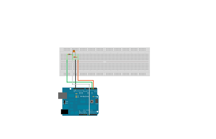
And my circuit is:


Sorry for making you to work, I hope you help me.

Thanks in advance.

Sorry, really sorry... I've write another post, I couldn't remember this. Really excuse me, It costs me a lot to control this forum, can I merge both topics?

this is the link of the other: [MERGED] Humidity Sensor HCH-1000 w/o TLC555? - Sensors - Arduino Forum

Peter_n:
If you are new to electronics, perhaps you better buy another humidity sensor.

The capacitance humidity sensors needs a pulse or frequency to measure the capacitance.
This shows a sketch Using an HS1101 humidity sensor - #6 by wildbill - Sensors - Arduino Forum and a schematic.
I hope you can read that schematic, it used 1M resistor parallel to the sensor and a 220 ohm to an Arduino pin.

Yes, I wanted to buy one SHT or some with 3 or 4 pins well documented, but the problem is that I don't have money at the momment. And it costs 13€ just the humidity and temp sensor, because the humidity only sensor is out of stock.

So, please, read the other post I've linked in my before answer to you, and maybe you understand why I am not using a TLC555. (because I thought it was possible without another IC).

If not possible, I will complain to keep money and buy a new one, just I wanted to take profit of this that my friend gave me. And said literally: "I don't understand how you can not make it working, I did easily". but he didn't said nothing about TLC555, and we were the weekend at home trying to work with it. So... sure he cheat me! :frowning:

Thanks for the answer, and sorry the time between answers.

Thanks to the moderator, the two topics are merged! Please, complain reading it, because I still doubt if some guy made it to work without TLC555...

I'm on my tablet now, so I can't open all the links easily.
Did you see the link in my Reply #1 ? and do you have a few resistors to test it. Do you get some values out of that sketch ?
You can put a damp cloth (not wet) on the sensor to see if something changes.

Oh, sorry. I missed it. Just already open.

I saw this sketch before while trying to get something clear.

Do you think this sketch is better idea than my actual one? Just to be sure, do you suggest me to try to calibrate the sensor by using the same circuit and sketch? Just doing the same that I did with my actual, (the way of calibrating by myself), would I get a better result? I see some light at the end of the path... :open_mouth:

Answering your question: yes, it's obvious to my eyes that the sensor is working, I can't ensure if it's working 100% well, but at the moment, it reacts by changing its value when the humidity changes. Example: breathing near the sensor, makes the output higher, and putting inside the bag with dry towel paper makes the sensor to output a lower value.

The problem is maybe the circuit and the sketch, which can't read well the variations, and only works with very higher changes...

Thanks Peter, I am going to try your suggestion (new circuit and code) but this time (because as said I saw it 2 days ago), I think I know what to do with the values of the "result" variable. :wink:

Another thing: do you think that I can "simulate" or to do something "similar" as the TLC555 would do, but without it? Even using more resources of the arduino, and doing a hard way coding... I am good at coding I think, but very bad in electronics because I never went to university. But started coding since very very young for computing. I know arduino is more powerful than the common way of coding, (IDE and C++), but ok, maybe it'll be very tedious... anyway, don't worry too much about this.

Thank you, I'm going to test and calibrate, and then I will show you my results.

Cheers!!!

EDIT: In the schematic of your link, the +5V seems to don't be connected, should I know where to connect it, or just he draw it for some other reason? In short words, must be +5V connected to somewhere?

Hello again Peter,

I've good news, I guess :slight_smile:

This is the output of the serial port:

accurate RCTime: 39.78
accurate RCTime: 39.75
accurate RCTime: 39.76
accurate RCTime: 39.75
accurate RCTime: 39.81
accurate RCTime: 39.76
accurate RCTime: 39.92
accurate RCTime: 39.80
accurate RCTime: 40.63
accurate RCTime: 40.43
accurate RCTime: 40.35
accurate RCTime: 40.06
accurate RCTime: 39.82
accurate RCTime: 39.77
accurate RCTime: 39.75
accurate RCTime: 39.76
accurate RCTime: 39.75
accurate RCTime: 39.76
accurate RCTime: 39.75
accurate RCTime: 39.76
accurate RCTime: 39.75
accurate RCTime: 39.76
accurate RCTime: 39.75
accurate RCTime: 40.03
accurate RCTime: 39.77
accurate RCTime: 40.69

This is the code:

int sensorPin = 4;              // 220 or 1k resistor connected to this pin
long result = 0;
void setup()                    // run once, when the sketch starts
{
   Serial.begin(9600);
   Serial.println("start");      // a personal quirk 
}
void loop()                     // run over and over again
{
  float rctime = accurateCapRead(sensorPin);
  Serial.println("accurate RCTime: " + String(rctime));
  delay(1000);
}

float accurateCapRead(int sensPin) {
  long rctime = 0;
  for (int i = 0; i<300; i++) {
    rctime += RCtime(sensPin);
  }
  return (float)rctime / 300;
}

long RCtime(int sensPin){
   long result = 0;
   pinMode(sensPin, OUTPUT);       // make pin OUTPUT
   digitalWrite(sensPin, HIGH);    // make pin HIGH to discharge capacitor - study the schematic
   delay(1);                       // wait a  ms to make sure cap is discharged

   pinMode(sensPin, INPUT);        // turn pin into an input and time till pin goes low
   digitalWrite(sensPin, LOW);     // turn pullups off - or it won't work
   while(digitalRead(sensPin)){    // wait for pin to go low
      result++;
   }

   return result;                   // report results   
}

The schema is: Using an HS1101 humidity sensor - Sensors - Arduino Forum

Now I have a question, are these output values, the RH %? Because my termo-hygro-meter says 42% now, and the last value is 40.45.

I'm going to test it inside the bag with the towel paper and let's see!

Thanks.

Ps: When I breath it shows different values, looks well. (haven't connected +5V as the schema says).

That is some output at least.
I'm not sure if that reading the value 300 times makes it more accurate.

In that schematic in Reply #1 is no +5V wire, because the Arduino charges and discharges the capacitor.

When you have a few samples, you could use the "MultiMap" to translate them in humidity percentage.
http://playground.arduino.cc/Main/MultiMap

In the reply #5 there's the schematic that I am using right now.

In the reply #1 I can not see any schematic, just is asking for documentation about the sensor, and a sentence more.

Well, thanks for the information about multiMap(), I've never seen before. But I'll try first with maths by hand, following the way I said before.

I have 2 measures, and I'll try to calibrate starting from 28 - 29% and 36-37 %. I'll post the results after.

Thanks Peter,
seems this is going to be the good one, I hope it.

Cheers!

Ps. Yes, maybe isn't accurate, I think it's a bit more easy to see at least. Maybe it is, but I doubt if it's accurately too. Just used 300 as random number, not very high, but also not very low. :wink:

This is my code, based on the before one.

Hope it helps.

int sensorPin = 4;              // 220 or 1k resistor connected to this pin
long result = 0;
void setup()                    // run once, when the sketch starts
{
   Serial.begin(9600);
   Serial.println("start");      // a personal quirk 
}

float min_rctime = 0.0;

void loop()                     // run over and over again
{
  /*
  float rctime = accurateCapRead(sensorPin);
  if (rctime > min_rctime) {
    Serial.println("accurate RCTime: " + String(rctime));
    min_rctime = rctime;
  }
  delay(100);
  */
  
  float rh = get_humidity(sensorPin);
  Serial.println("Humidity: " + String(rh) + " %");
  delay(1000);
}

float accurateCapRead(int sensPin) {
  long rctime = 0;
  for (int i = 0; i<300; i++) {
    rctime += RCtime(sensPin);
  }
  return (float)rctime / 300;
}

float get_humidity(int sensPin) {
  float rctime = accurateCapRead(sensPin);
  float rh = map(rctime, 20.8, 70.8, 0, 100);
  return rh;
}

long RCtime(int sensPin){
   long result = 0;
   pinMode(sensPin, OUTPUT);       // make pin OUTPUT
   digitalWrite(sensPin, HIGH);    // make pin HIGH to discharge capacitor - study the schematic
   delay(1);                       // wait a  ms to make sure cap is discharged

   pinMode(sensPin, INPUT);        // turn pin into an input and time till pin goes low
   digitalWrite(sensPin, LOW);     // turn pullups off - or it won't work
   while(digitalRead(sensPin)){    // wait for pin to go low
      result++;
   }

   return result;                   // report results   
}

Thanks Peter,
cheers!

Ps. I'm still testing it, maybe tomorrow I can ensure it's working well.

How did I get the MIN and MAX?

SVT1: sensor value, in the ambient of home.
SVT2: sensor value, in the bag.
RHT1: termo-hygro-meter value, in the ambient.
RHT2: termo-hygro-meter value, in the bag.

Once we have those 4 values, we can proceed to get MiN and MAX.

R (elation) = (SVT1 - SVT2) / (RHT1 - RHT2) = R
MiN = SVT2 - R * RHT2
MAX = MiN + 100 (%) * R

Hope it helps.

EDIT
Hello all,

the sensor was working the whole night, but my physics are horrible. Lol.

The true is that inside the bag the sensor arrived to the near 0%, so the maths are different.
Just for calibrating, put inside the bag, take the lowest value, and this is the minimum output from the capacitor, and indicates 0% humidity.
Then take it out, and put near a termo-hygro-meter or hygro-meter, wait until a stable value from it, and take the most repeated value from the cap.
Or just do the trick of boiling water for getting 100%, or have a shower with the sensor ;).

If you don't want to spend more time, do the following maths for getting MAX value:

My HCH-1000 says 35.05 inside the bag (0%).
My hygrometer says 39% outisde the bag.
My HCH-1000 says 39.3 outside the bag, at same time hygrometer says 39%.
Then: MAX = 35.05 + 4.25 / 39 * 100 = 45.94
4.25 is the difference between 0% and 39%: 39.3 - 35.05.

Now seems to be working even better and faster than my hygrometer ;).

VERY IMPORTANT
Try to calibrate it with the final circuit and arduino board, try to don't change cable sizes.
Once calibrated, if you for example change the board from 2560 to Leonardo (for example), it'll need another calibration. Due to the speed of each board. RCtime is going to return different values. Also try to don't add too much code as interrupts, after calibration... it will affect too.

If you don't want to pain a lot, buy a TLC555 and the resistors, caps, etc needed for making it to work as the manufacturer says. The links is up of the thread.

Good luck, and have fun.

Thanks for letting us know. Very good result.

Interrupts will have influence on the result. The internal timing of the Arduino, and the Serial and the I2C (Wire library) use interrupts.
If you don't need interrupts during measuring, you can turn them off with : detachInterrupt() - Arduino Reference and back on with : http://arduino.cc/en/Reference/Interrupts

When I wrap a damp cloth around a humidity sensor, it is getting near 100% humidity.
I have bad results with DHT11 and DHT22. One of my DHT11 is always 30 or 31%, while it should change between 40 and 80%. A capacitive sensor is certainly better than those with a humidity sensitive resistor material.

P.S.: I use the link "Updated Topics" in the upper-right-below-header of the page to check for new messages. When you edit a message, I don't see it. So please just add a new reply, even if it is only a few words.

Damn, That's the way I am so crazy lazy clever.

That's not true, I am just a good guy, I want to show you a lot of information about programming, and arduino with electronics. Oh, Also, the word of Arduino is not recognized (red underlined).

Mate, I'm still doubting. About the sensor, is making me crazy, works like a charm, or just it's crazy broken.

My hygrometer says min and max very different from the sensor. But when the hot air is blowing around the inside's saloon, I can not believe how the humidity is updated in less than 4 minutes. And it's stable until the temperature changes again. That's the way I am saying I am so crazy lazy clever, but it's the problem. This is not working well, I guess even without interrupts.

Because, I need to know, now that I now that the range of measurement of the sensor, is from 0 to 100 RH %

But, just taking the difference between low measures, and knowing my hygrometer is very slow... I think, maybe a good improvement would be to use a 3V battery, instead of 1.5V. But maybe it will burn.

The true, is that my hygrometer says min 30% but it can't measure under 28%
That's the way I was confused. Because the 0% is completely relative and true.

Another problem, is that the speed of the board can read even faster than the others, if speaking about mega2560 compared to ATMEGA328P.

But, I don't have TLC555 that would make the sensor, generic. With a very complex circuit. For me, at least, very hard to read if using that small size. And as I said, I am a newbie.

What I would do?

Just, to reach the 100% tonight. Again, calculate, use the same board, telecommunicate with the server over the air,
and then, response back to the controller. Which controls the power rails of the humidifier and other altern current electronic components.

So, I will use mega 2560, which I really love as it was a present, and my first Arduino. But I had to repair it =).

The wires are just 0.1 mm thick, and ~16cm long.

I use 2 wires, brown and green. Green is Analogue Input, brown is GND.

I used 220Ohm resistor in serie with a 1Mohm resistor in pararlel with the cap. HCH-1000 is the cap.

This humidity sensor, is crazy accurate, faster and bravely optimized. But I must recalibrate again. It's over 6% difference between "real" measurements, and between a range of 23% and 42%.

Well, I am writing a new comment every time to answer you. I am thinking always in global.

thanks for the reply, I was wondering to had news from you yesterday night, but obviously it wasn't accurate ;).

Cheers,

abel.
I want to thanks all the community, I am having the best times in my life at the moment, and I can't say how many I am glad to receive responses and discovering new material every time I go inside.

really appreciated. <3

Omg, I want to sleep but I need to finish this... I am going to try the same code without interrupts.

So we have this now:

long RCtime(int sensPin){
    noInterrupts();
   long result = 0;
   pinMode(sensPin, OUTPUT);       // make pin OUTPUT
   digitalWrite(sensPin, HIGH);    // make pin HIGH to discharge capacitor - study the schematic
   delay(1);                       // wait a  ms to make sure cap is discharged

   pinMode(sensPin, INPUT);        // turn pin into an input and time till pin goes low
   digitalWrite(sensPin, LOW);     // turn pullups off - or it won't work
   while(digitalRead(sensPin)){    // wait for pin to go low
      result++;
   }

   interrupts();
   return result;                   // report results   
}

This is a sample output, with an LM35 temp sensor.

Temperature,Humidity (COM10):

20.18,36.25
20.18,36.19
20.16,36.25
20.17,36.25
20.17,36.22
20.17,36.19
20.17,36.22
20.19,36.25
20.22,36.25
20.21,36.22
20.20,36.25
20.19,36.19
20.19,36.19
20.22,36.25
20.23,36.22
20.22,36.22
20.23,36.22
20.24,36.25
20.22,36.19
20.23,36.22
20.24,36.25
20.23,36.25
20.23,36.25
20.22,36.22
20.26,36.22
20.24,36.22

And this is what I had before disabling interrupts.

Temperature Now MIN (ºC) MAX (ºC)
20.29 19.41 25.32

Moisure Now (RH %) MIN. (%) MAX. (%)

33.89 23.86 42.85

The hygrometer says: 35%