How to have up to 30V from 0-5v analog output low current

Hi

I need a very easy way to convert 0-5v from "analog" output in arduino nano to 0-32v proportional ... no big current , since it is just a signal.
So when output pin is 5v (or pwm 255 ) then I should have 32v output and 128 value should be 16vol....and so on.... i mean maybe call it a programable level shifter.... any idea? thks veryyyy much.

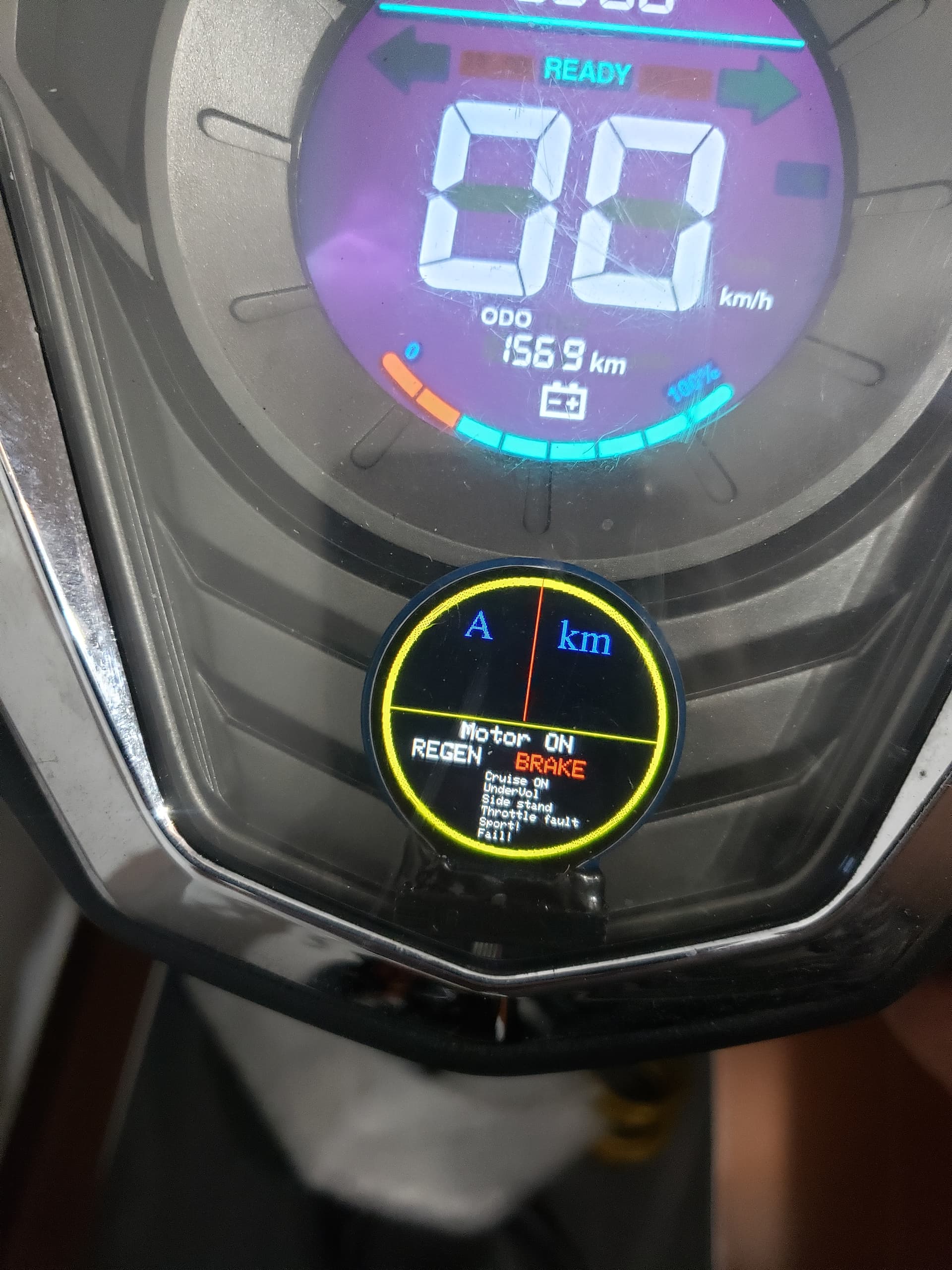
use is for a bike speedometer whose signal is from 0 to 32vol and its display is 0to50kmh.
now i want to control from the arduino.

Classic nano doesn't have analog output, it can output 5V PWM.
What about 0-32V? Can it be 32V PWM as well? Then you could use optocoupler for example.

Does you bike have 32VDC avaliable somewhere or maybe 48VDC?

i would be able to grab 36 or 48v from battery cells maybe.... so 10s would be 42v fully charged... it is a scooter in fact, so runs at 84v.

and...Not clear to me what optocoupler would work here

Put some numbers on how fast the signal needs to change, both up and down!

wel it is a normal speeemeter, so i think 1 hz ? one time per second should be enough.... if I understood your question.

Thank you. That tells how much time any circuit has to react.

You didn’t say ‘electric’ scooter, but you did say 84V, and that pretty much rules out internal combustion engine.

An electric scooter will inevitably use electronic motor management that internally works with probably 5V or 3.3V. I expect the speedometer to use that as signal voltage. A supply voltage of 84V isn’t logical but not impossible, so more info is needed.

Look more closely at the speedometer, can you find a part number? How many connections does it have and how are they labeled? Photos would be nice.

yea i can show this picture but forget about the uses and if you could help just with a simple circuit that from arduino pwm 5v output can mimic a 0 to 32v proportional signal

the big numbers in the display are the ones that I want to change with those 32v = 50kmh...and 16vn=25km and so on..... this is atock apeedmeter

i replaced the controller but it expects analog volts (the speedmeter i mean)

the rounded display at the botton is a digital serial interface i did with can bus like signal in arduino but it is not stock and will be removed

Yes or No? You will need a source for the high voltage for my circuit to work.

yes of course, i can have 12 24 36 48 up to 96v available.

OK
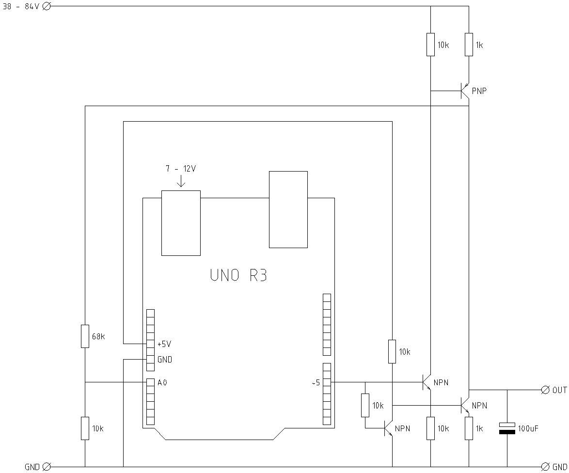
There probably is no easy way for you to do this. I don't see any way of doing it with off-the-shelf modules/boards. It is possible to build a circuit using a few opamps, transistors, voltage regulator, resistors, etc.

1 Like

thanks you then.and using eg arduino uno r4 minima that incorporates a DAC?

I still don’t know how your instrument works. But producing a voltage up to 32 V is not too complicated. Be sure that you use components that can withstand the supply voltage you’re using.

/* for speedometer, output = 32V at 50kM/h */

#define pinPWM 5
#define pinFeedBack A0
#define speedCalibration 50  // 50kM/h
#define adcCalibration 840   // 32V, 10kOhm, 68kOhm
#define pwmCalibration 210   // assuming linear relationships: adcCalibration * 1024 / 256
uint8_t mySpeed = 0;
uint8_t myPWM = 0;
uint32_t previousCalculation = 0;
uint32_t intervalCalculation = 50;  // adjust every 50ms


void controlPWM() {
  if (mySpeed == 0) {  // stand still
    myPWM = 0;
    analogWrite(pinPWM, myPWM);
    return;
  }
  if (myPWM == 0) {  // calculate start value, assuming linear relationships
    myPWM = map(mySpeed, 0, speedCalibration, 0, pwmCalibration);
    if (myPWM == 0) myPWM = 1;
    analogWrite(pinPWM, myPWM);
    return;
  }
  // calculate new value
  uint32_t adcDesired = map(mySpeed, 0, speedCalibration, 0, adcCalibration);
  uint32_t adcActual = analogRead(pinFeedBack);
  myPWM = myPWM * adcDesired / adcActual;  // calculation in 32 bit numbers
  if (myPWM == 0) myPWM = 1;
  analogWrite(pinPWM, myPWM);
  return;
}

void setup() {
  // put your setup code here, to run once:
}

void loop() {
  if (millis() - previousCalculation >= intervalCalculation) {
    controlPWM();
    previousCalculation += intervalCalculation;
  }
  // put your main code here, to run repeatedly:
}
1 Like

That would make things simpler.
If I draw a schematic will you know how to build it?

Stitech thanks I will try it of course.... looks promising. i have a Uno r3 here (not a R4 minima) to test with.... also those npn can be any also smd? .... the iinstrument is like a tester.... it is very common in cheapss electric scooters and ebikes.... works with a volt variable if you provide 1V your display will show 1kmh. if you go to 2v then 2kmh... it is not limear so around 30V it will show 42kmh and 60v around 86kmh.
the new controller i bought is capable of send real speed and amps in a data line that is the reason why of the lower round display but the bigger display is stock one and only works with this 0v to xxV to show kms/h in 0 to 100km range (0v to around 62v)
so if your sketch works for me i will adapt to output at pin5 the value i want according to the real speed in the data line arduino has from serial input ...
So the idea is to replsce my current arduino nano that works with the lower round display to show amps and volt from data line (received from the controller) with your UNO R3 and the speed data from pin2 is available to produce this "almost linear" volt output to the speedmeter!...
i will see where can i fit in the code the pin2 data of the speed to produce the required output volt.

thanks i hope cleared the way ir works
just in case:

bike: sunra hawk
new controller: votol em100
round tft; common 1.28" with nano
volt pack: 88v

I realized that my circuit wouldn’t do well for low output voltages. So I changed the current sources for current mirrors. I also added a constrain() function to the sketch.

/* for speedometer, output = 32V at 50kM/h */

#define pinPWM 5
#define pinFeedBack A0
#define speedCalibration 50  // 50kM/h
#define adcCalibration 840   // 32V, 10kOhm, 68kOhm
#define pwmCalibration 210   // assuming linear relationships: adcCalibration * 1024 / 256
uint8_t mySpeed = 0;
uint8_t myPWM = 0;
uint32_t previousCalculation = 0;
uint32_t intervalCalculation = 50;  // adjust every 50ms


void controlPWM() {
  if (mySpeed == 0) {  // stand still
    myPWM = 0;
    analogWrite(pinPWM, myPWM);
    return;
  }
  if (myPWM == 0) {  // calculate start value, assuming linear relationships
    myPWM = constrain(map(mySpeed, 0, speedCalibration, 0, pwmCalibration), 0, 255);
    analogWrite(pinPWM, myPWM);
    return;
  }
  // calculate new value
  uint32_t adcDesired = map(mySpeed, 0, speedCalibration, 0, adcCalibration);
  uint32_t adcActual = analogRead(pinFeedBack);
  myPWM = constrain(map(mySpeed, 0, speedCalibration, 0, pwmCalibration), 0, 255);
  analogWrite(pinPWM, myPWM);
  return;
}

void setup() {
  // put your setup code here, to run once:
}

void loop() {
  if (millis() - previousCalculation >= intervalCalculation) {
    controlPWM();
    previousCalculation += intervalCalculation;
  }
  // put your main code here, to run repeatedly:
}

Did you ever test if it's happy with pwm? Like arduino analogwrite.

I edited the sketch:

/* for speedometer, output = 32V at 50kM/h */

#define pinPWM 5
#define pinFeedBack A0
#define speedCalibration 50  // 50kM/h
#define adcCalibration 840   // 32V, 10kOhm, 68kOhm
#define pwmCalibration 210   // assuming linear relationships: adcCalibration * 1024 / 256
uint8_t mySpeed = 0;
uint8_t myPWM = 0;
uint32_t previousCalculation = 0;
uint32_t intervalCalculation = 50;  // adjust every 50ms


void controlPWM() {
  if (mySpeed == 0) {  // stand still
    myPWM = 0;
    analogWrite(pinPWM, myPWM);
    return;
  }
  if (myPWM == 0) {  // calculate start value, assuming linear relationships
    myPWM = constrain(map(mySpeed, 0, speedCalibration, 0, pwmCalibration), 1, 255);
    analogWrite(pinPWM, myPWM);
    return;
  }
  // calculate new value
  uint32_t adcDesired = map(mySpeed, 0, speedCalibration, 0, adcCalibration);
  uint32_t adcActual = analogRead(pinFeedBack);
  myPWM = constrain(myPWM * adcDesired / adcActual, 1, 255);
  analogWrite(pinPWM, myPWM);
  return;
}

void setup() {
  // put your setup code here, to run once:
}

void loop() {
  if (millis() - previousCalculation >= intervalCalculation) {
    controlPWM();
    previousCalculation += intervalCalculation;
  }
  // put your main code here, to run repeatedly:
}

thanks im preparing it to feedback you