Hey you all, i do some customo cars and eletronics its not my deal. im building a adaptor to make a new vw sunroof with old vw switch, the old one is a push type switch, so to open you need to keep on of the 3 buttons pressed, in the new sunroof it is a rotary switch, so you put in position and its go to. i already have the old buttons sending the push to arduino, it reads the info and make a output, with analog write in pin 5 like code below.
  if  (buttonState1 == LOW) {
    Serial.println("TOP_UP");
    analogWrite(output1, 28);
  }
  else if (buttonState2 == LOW) {
    Serial.println("CLOSE");
    analogWrite(output1, 112);
  }
  else if (buttonState3 == LOW) {
    Serial.println("OPEN");
    analogWrite(output1, 255);
  }
i know that arduino don't have enough power to run this outputs. Now my problem it's how can i solve this the most simple and cheap way? i have small space for the electronics. i can use more pins if needed, but in the car motor its 1 wire for the input. so to puts 3 pins in same wire if i need, how to do this to?
Because i connected and when I push the button in the multimeter it don’t reach the voltage that it’s suppose to be, without the motor connected it’s right.
Yes maybe isn’t to be pwm, was a try, I’m not an electronic guy, have limited knowledge about. Need to study more about this.
But what’s the easy/simple way to solve this? Need just 3 voltages output to
Make this work.
You can't power a motor from arduino.
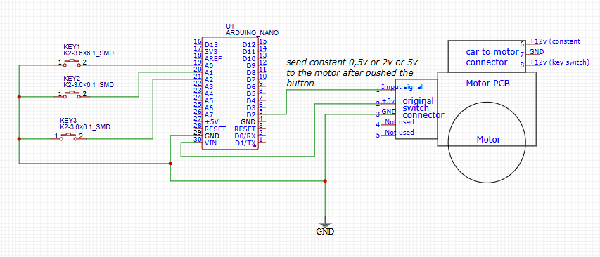
If you need help here, I suggest you to post a scheme of your circuit and detailed description what you are trying to accomplish.
If you press SW1, you will have 5V on pin 1 of J1.
If you press SW2, you will have 2V on pin 1 of J1.
If you press SW3, you will have 0.5V on pin 1 of J1.
For the 2V, the formula would be 5V * (R2 + R3) / (R1 + R2 + R3)
For the 0.5V 5V * (R3) / (R1 + R2 + R3)
If you want to use the 12V of your car, you can add an additional resistor above R1 and adjust the formulas to take it into account. I can not advise on car electronics, it's dirty stuff.
Ok so where i get the 5v from? arduino can handle the current, so need be from the motor pcb 5v, but how it trigger to send this constant voltage to the signal input? because it must be constant, not a push. hope make my self understandable
Just a little up date that i forgot to post the code im using and "works" but with not enough power to signal make the pcb of the motor to understand.
const int buttonPin1 = A0;
const int buttonPin2 = A1;
const int buttonPin3 = A2;
const int buttonPin4 = A3;

const int saida1 = 5;

int buttonState1 = 0;
int buttonState2 = 0;
int buttonState3 = 0;
int buttonState4 = 0;

void setup() {

  Serial.begin(9600);

  pinMode(buttonPin1, INPUT_PULLUP);
  pinMode(buttonPin2, INPUT_PULLUP);
  pinMode(buttonPin3, INPUT_PULLUP);
  pinMode(buttonPin4, INPUT_PULLUP);

  pinMode(saida1, OUTPUT);

}

void loop() {
  buttonState1 = digitalRead(buttonPin1);
  buttonState2 = digitalRead(buttonPin2);
  buttonState3 = digitalRead(buttonPin3);
  buttonState4 = digitalRead(buttonPin4);


  if  (buttonState1 == LOW) {
    Serial.println("TOPETE");
    analogWrite(saida1, 28);
  }
  else if (buttonState2 == LOW) {
    Serial.println("FECHADO");
    analogWrite(saida1, 112);
  }
  else if (buttonState3 == LOW) {
    Serial.println("ABERTO");
    analogWrite(saida1, 255);
  }
}
I was thinking, can i use a transistor (have done some research and i understand that transistor just give ground output, so i attach a transistor to the resistor circuit that sterretje post above, but using 3 pins to do that and then those 3 outputs from the resistor come together to the signal input in the motor pcb maybe using some diode ich one of the 3 wires? its that possivel or i'm complicating? maybe a mosfet? i dont understand it well but he have a positive output? or a relay? like i say, i'm starting now with this kind of electronics, and need to study and lerd a lot. thanks for the patient of all you guys.
remember that i want to keep using the arduino, because i want to use it for more stuff in the system, like turn on the lights and a alarm signal to close the roof. thinks like that.
The circuit @sterretje posted, should work, you just keep the button pushed until the action is complete.
Also, how you know the problem with arduino is current? Did you measure the current draw of direct 5V to signal pin? What if it doesn't like PWM and needs true analog signal?
how? its the same problem and need. i don't get it sorry. how im changing my goal?
It will not because it need to keep the current, if i release the button it will send 0v and the motor pcb will move the motor to 0v position. it need to keep the voltage after i "click"/press the button and change to other voltage when i press the other button.
but you are right it need true analog signal, so thats my question, how can i get 0,5v, 2v and 5v analog to the same signal wire with the arduino pinout?
You started want an Arduino to generate several voltages for you. Then the solution of a set of voltage dividers and switches would solve your problem. That seems to had brought the solution back to an Arduino, again. So there is a lot more to your project that just supplying several voltages with switches.
but i never said that i want to use divider and switch, i always want to keep the arduino, use to read the alarm signal, led and can data to make more stuff. other user suggest that i use switches and a divider. i just need help with this detail, how i can make this 3 voltage work with the arduino.
make it more simple, can use my arduino, my code can be changed no problem, my hardware too, just how can i make with a push button with arduino i get a stable voltage in my motor pcb to it understand the signal and move it?
Replace the switches in the voltage divider example with optocouplers driven from digital pins on your Arduino. Then use the arduino to close the relevant "switch".
You can also add manual switches in parallel with the input side of the optocouplers to allow you to manually activate the motor if needed.
[Edit: clarifying to add the manual switches to the input side of the optocouplers]