How simple or complex is it to program a digital pot? I am using the AD5160 and I saw an example on the Arduino site for the AD5206.
I also saw this library on github that was used for the AD5161 AD5161.
So far I do not have the AD5160 on hand but I just ordered it and was programming before it arrived. This is what I have so far. Any look over is much appreciated.
/* Using a TEENSY 4.1 board*/

#include <Streaming.h>
#include <SPI.h>

#define CS          10        //Chip Select pin for Digi Pot
#define POT_MAX     255       //max Digi Pot value

elapsedMillis timeTriggerA;         //teensy 4.1 board library
elapsedMillis timeTriggerB;         //teensy 4.1 board library

void setAD5160Resistance(byte value) {
  /*--- Function to set the resistance value on the AD5160 ---*/
  digitalWrite(CS, LOW);      // Select the AD5160
  //SPI.transfer(0x11);                         // Command byte to update the resistance
  SPI.transfer(value);                        // Send the value to set the resistance (0 to POT_MAX)
  digitalWrite(CS, HIGH);     // Deselect the AD5160
}

void setup() {
  pinMode(CS, OUTPUT);
  digitalWrite(CS, HIGH); // turn spi device 1 off initially

  Serial.begin(115200);
  SPI.begin();

  while (!Serial) {
    ; // wait for serial port to connect. Needed for native USB port only
  }
}

void loop() {
  for (int i=0; i<256; i++){
    setAD5160Resistance(i); //change the value to change the resistance
    Serial << i << endl;
    delay(5000);
  }
}
If you have time, a quick look at the data sheets for the two parts might show they are used identically.
Or not. Imma guess two digipots from one manufacturer are going to respond to the same code.
And
delay(5000);
is going to start feeling like an eternity. There is no limit as to how fast you can set the value again, so use 100 if your main goal is to stop the spamming that full speed would cause.
Generally digipots are super easy to use. Library or no. Personally I write this kind of stuff without using a library, it is my version of fun.
The harder part of digipots is making sure you are within the voltages and current it can tolerate. In this way they are very different to real pots.
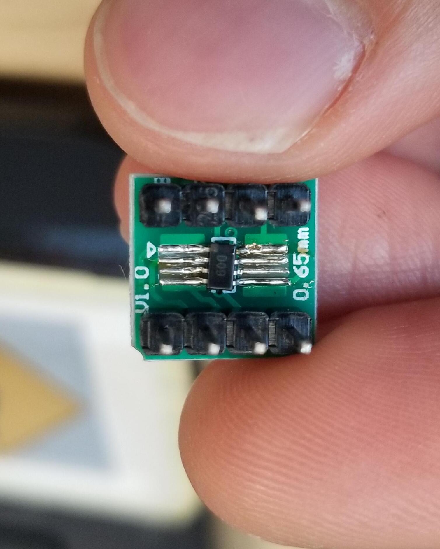
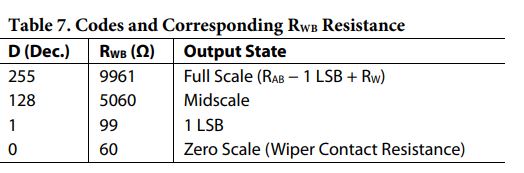
I made sure there were no shorts between pins by doing a continuity test. Is there a way to read the resistance value from a digi pot via 3-wire spi? The table in its datasheets states that it has resistance readings based on the 8-bit digi code you send it.
I ended up measuring pins B and W with a multi-meter. I believe it is working since changing the 8-bit digi code to 255 gives me 10k ohm, and I am using a 10k ohm digi pot. Now I think I just need to correlate the resistance values to the voltages I want to output.
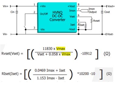
I am not familiar with DAC. I am using the digital pot to feed a resistance to a dc-dc converter. The converter can alter its dc output based on the resistance I have on its Vset pin.