The detector has a data pin (W8), 5V and GND rails. From some measurements, here is how W8 behaves:
When nothing is detected, W8 produces 5V.
When something is detected, W8 produces 0V.
My objective is to create a circuit where I can read this data on pin 14 of the Arduino and control an LED on pin 19 based on the input.
A SOLUTION
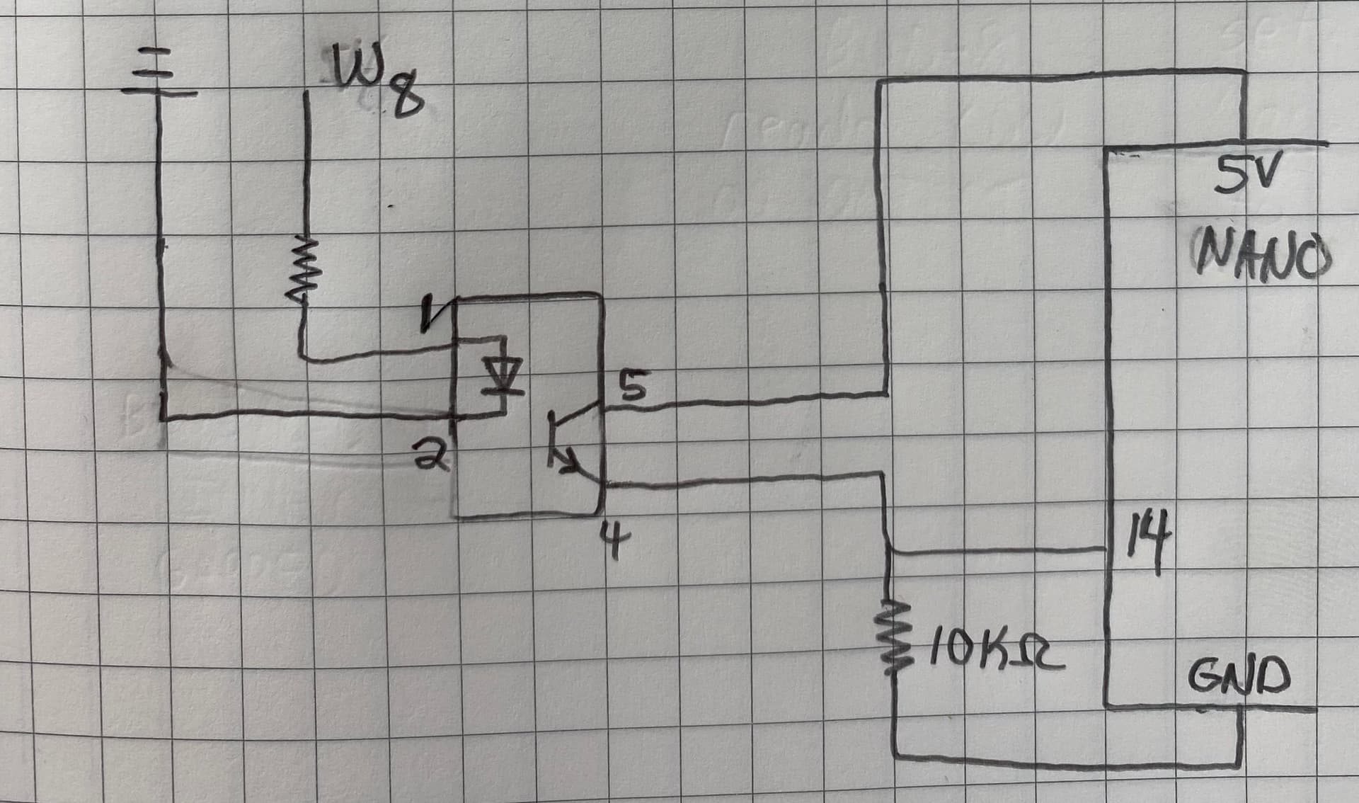
I have built a working circuit using an 4N35 Optocoupler. I will post the circuit in the thread below since new users are only allowed a single image.
Since I was unsure how to wire the two circuits together, I figured using something like an optocoupler to isolate the two circuits would be the safest solution for the moment.
QUESTIONS
While this solution works alright for a single data pin (W8); the device actually contains 8 data pins. With the optocoupler solution above, it feels like expanding this circuit would get quite large.
Is there a more straightforward circuit that should be used in situations like this?
This last picture shows a circuit that ought to work.
For DC signals from W8 You can use voltage dividers for reasonable voltage signals, not mains levels.
The resistor connected to W8 is needed to control the current through the optocoupler input LED, and must be less than 50 mA. 5 to 10 mA would probably be reasonable, in which case you might use 330 Ohms.
Wires work, IF you can share the ground connection, AND both devices are always powered at the same time AND both devices have 5V I/O. Otherwise, an optocoupler is a good solution.
If you have 8 outputs from the mystery device you could use one 8-bit parallel-in serial-out shift register to grab them all at once (latch), and 3 pins on you Nano to clock them in (latch, clock and data).
If you have access to the code of the msytery device, you could use serial protocol communication and send all 8 bits as one character and receive same character on the Nano.
If you connect the optocoupler transistor between an Arduino input and ground, you use INPUT_PULLUP to enable the inbuilt pullup. The LED resistor needs only provide about 2 mA in this case - 1k8.
And you can connect the optocoupler LED and resistor between 5 V and the output so it is actuated when the output goes to 0 V.
Please do not purchase obsolete 4N35 optocouplers.
Put a 4k7 resistor between each output of the first and input of the second for protection.
Always a good idea to explain just what these devices are if you wish to know about better solutions.
The device is a DCC current detector made by RR-Cirkits used in model railroading. The manual can be found here.
How much current can W8 supply?
The vendor specifies that each data pin (I have labeled W8) can supply up to 15mA at 4.5V. In my circuit for the unlabeled resistor in series with W8 I have been using a 560 ohm resistor.
Wires work, IF you can share the ground connection, AND both devices are always powered at the same time AND both devices have 5V I/O.
While the devices are powered at the same time and [seem to?] both have 5V I/O, I was less sure about whether the ground connections could be shared.
Section 10 of the device's manual says things like:
Normally all WatchMan connections originate or reference to the WatchMan board
itself, so there is no danger of ground loops. RR-CirKits High power output boards
are opto isolated from the WatchMan port and use their own power sources.
If you are building your own I/O boards or using third party units be sure to
observe the common/isolated ground rules, and never exceed 5V on any pin.
Since I was unsure about these rules, I played it safe and used the optocoupler.