I am working in a project where I need to manage a good amount of GPIO as outputs, I am running out of pins and I need to use the SDA pin as an Output, I tried some configurations that I found in this forum like using:
pinMode(SDA, Output
or
PORT->Group[g_APinDescription[SDA].ulPort].PINCFG[g_APinDescription[SDA].ulPin].bit.PMUXEN = 0;
but none of this apparently solve my problem, the pin will be connected to the base of a 2n222A transistor to manage a relay, whit other pins that I used for the same purpose I did not have any problem, when I put any pin to LOW, the voltage in those pins is 0.00 but when I try to do the same with the SDA pin the voltage that is present when I send the LOW command is 1 volt
Any help with this matter I really appreciate
If I'm interpreting this schematic correctly, there are 4K7 pull-ups on the SDA & SCL pins of the board
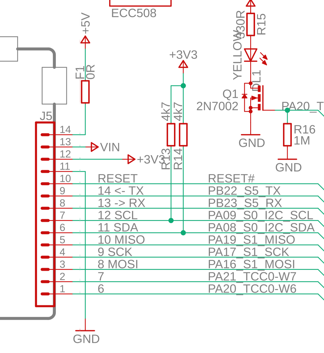
But... setting the SDA pin to low should still result in 0V output. Please post a schematic showing how the pin is connected, and a link to the specs of the relay board. Could there be a pull-down resistor on the relay board?
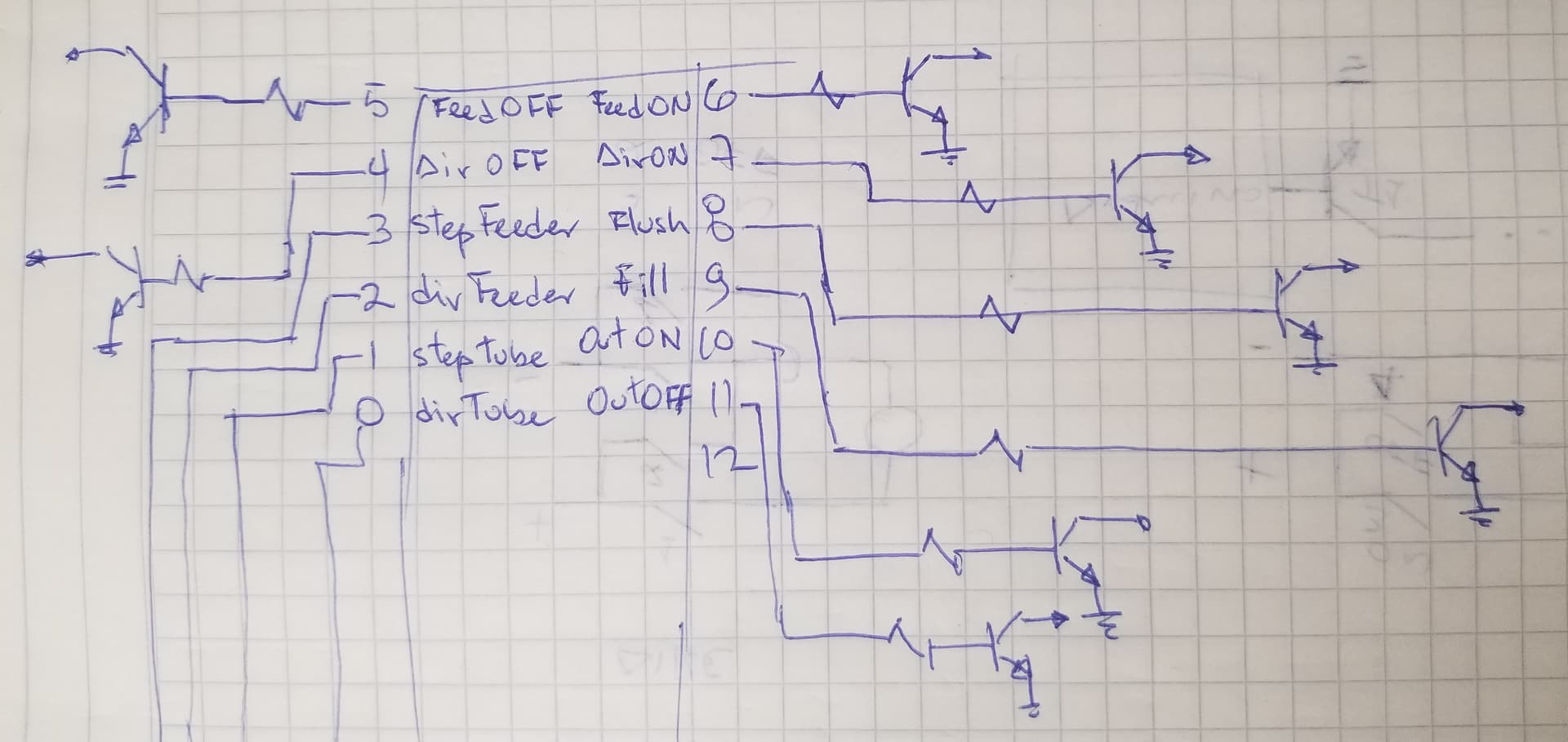
Thanks for your answer, I am using 8 pins of the GPIO to control the relays(SDA included), all other 7 pins works without problem, I am enclosing a hand drawing of how I am connecting the GPIO to the input control of an "Arduino relay module"
I found a schematic of the relay board in this link
I try connecting in a protoboard only the circuit with the transistor without the relay and still I obtain that 1 volt at the output
This topic was automatically closed 180 days after the last reply. New replies are no longer allowed.