Can somebody help me with my project ? I need to simulate an absolute encoder with a Arduino Nano. I can find a lot of code to read encoders, but nothing to simulate one.
The signal needed is a SSI (Synchronous Serial Interface), 25 bit, binary...
I really need help to find reference or hint or anything please !
Maybe someone will prove me wrong, but you will need to use something else.
When you say something else, you mean something else than an Arduino or in addition with it ?
From what I can tell, in stead of.
I need to simulate an absolute encoder with a Arduino Nano
The signal needed is a SSI (Synchronous Serial Interface), 25 bit, binary...
What is going to be reading the encoder/nano simulator?
I have used digitalRead() in code like below and it gets the timing correct
stream[25] = {0};
  for (int i = 0; i < 25; i++) {
    digitalWrite(PIN_CLOCK, LOW);
    digitalWrite(PIN_CLOCK, HIGH);

    stream[i] = digitalRead(PIN_DATA);
    //can construct data sum here
  }
I think that if the nano were reading the clock and then writing out to the data pin a high or low it could work. You might have to work on the syncronization or slow things down.
How will the nano know what data to send?
What will read the signal is a RMC150 SSI card
(RMC150 SSI Module)
In fact, the Nano will act as a Linear Transducer and the only data to send is an absolute 25 binary bits position, which will go up and down in a known range.
(SSI Fundamentals)
That way, it's gonna be possible to trend the signal in the RMC program and see a triangle waveform... Now I can see something on the trend but it is erratic and unpredictable. I'm using an ISR with a changing variable than I write in the SPDR... but it's not working well... Not as I want it to be...
Thank you very much for your help !
Thanks for the information. You are probably the world's expert on what you are trying to do, but I can try to listen an provide some feedback.
In fact, the Nano will act as a Linear Transducer and the only data to send is an absolute 25 binary bits position, which will go up and down in a known range.
I assume you have the nano communication to RS422 worked out.
From the link you posted
To read an SSI position, the RMC sends clock pulses to the transducer and the SSI device returns the data as follows:
The SSI channel sends the first clock pulse by setting the Clock signal low, then high.
On the first rising edge of the Clock signal, the SSI transducer returns the most-significant bit of the data on the Data line.
The SSI channel sends the second clock pulse by setting the Clock signal low, then high. When the Clock signal goes high, the SSI channel samples the bit on the Data line. When the SSI device sees the clock signal go high, it places the second bit of data on the Data line.
This continues until all bits have been clocked and sampled.
Can you post the code for the Nano which reads the clock signal interrupt and sends a bit to the data line?
I'm using an ISR with a changing variable than I write in the SPDR... but it's not working well... Not as I want it to be...
I don't understand what this means? What is SPDR?
This came up in another thread today.
Thank everyboby, I'm making very good progress with your help !
Here's the code :
#define SSELECT 10//SS
#define DATAOUT 12//MISO
#define CLOCK 13//sck
volatile byte absbuffer = 0 ;
volatile int signalvalue = 0;
volatile bool directionUP = true ;
void setup (void)
{
pinMode(SSELECT,INPUT);
pinMode(DATAOUT, OUTPUT);
pinMode(CLOCK, INPUT);
SPCR = (1<<SPIE)|(1<<SPE)|(0<<DORD)|(0<<MSTR)|(1<<CPOL)|(0<<CPHA)|(1<<SPR1)|(1<<SPR0);
} // end of setup
// SPI interrupt routine
ISR (SPI_STC_vect)
{
if (directionUP == true ) {
signalvalue = signalvalue + 1 ;
if (signalvalue >= 2550) directionUP = false ;
}
if (directionUP == false ) {
signalvalue = signalvalue - 1;
if (signalvalue <= 0) directionUP = true ;
}
absbuffer = signalvalue / 10;
SPDR = absbuffer;
} // end of interrupt service routine (ISR) SPI_STC_vect
void loop (void)
{
} // end of loop
It is working, I can see a count in my RMC, but the problem is I'm sending 8 bits ... so the count from 0 to 262144 and then go up and down...
So I need a way to send 25 bits... any ideas ?
So I need a way to send 25 bits... any ideas ?
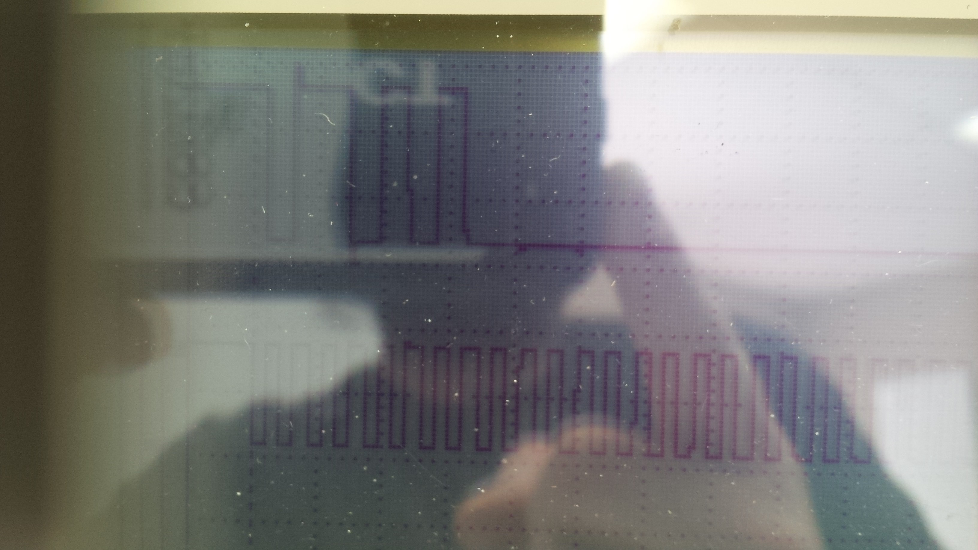
I do not think you are going to get there using SPI. When I look at you scope image of the serial clock, which is controlled by the RMC, I see the long string of clock pulses with no indication that it is using a protocol related to hardware SPI.
I haven't seen any example of code which pushes new data into SPDR without bidirectional communication or gaps in the clock stream.
I think that the approach taken by the Sam Siefert in the link I provided is in line with my original thoughts that the nano should read the clock and then write out to the data pin a high or low.
I'm sure its not what you want to hear, but I believe that your best path is to give up on SPI and use the nano to bit bang the data in response to the clock.