Hello Arduino Community,
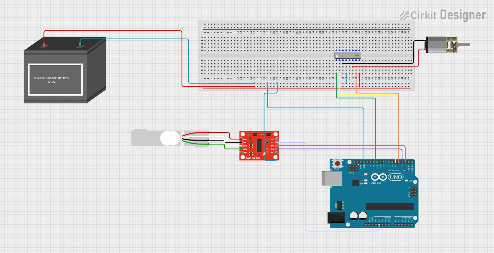
We are currently facing an issue with our setup using an Omega strain gauge compression load cell with an excitation voltage of 10V, connected to an HX711 amplifier, interfaced with an Arduino. Despite following the standard procedures, the voltage readings from the load cell are constant and do not change when the load cell is touched or loaded. We have ensured that the load cell and amplifier are undamaged by swapping components.
Here is the code we are using to calibrate the load cell and read voltage:
#include "HX711.h"

// Pin definitions
const int LOADCELL_DOUT_PIN = 2;
const int LOADCELL_SCK_PIN = 3;
const int MOTOR_ENABLE_PIN = 9;
const int MOTOR_DIR1_PIN = 4;
const int MOTOR_DIR2_PIN = 5;

HX711 scale;
float V_excitation = 10.0; // Excitation voltage in volts
float load_cell_sensitivity = 2.0 / 1000; // Load cell sensitivity in mV/V per volt of excitation

int i;

void setup() {
  Serial.begin(9600); // Initialize serial communication at 9600 baud
  scale.begin(LOADCELL_DOUT_PIN, LOADCELL_SCK_PIN);
  scale.set_scale(); //Set the scale (calibration factor) to 1 initially
  scale.tare(); // Reset the scale to 0

  // Motor pins setup
  //---set pin direction
  pinMode(MOTOR_ENABLE_PIN,OUTPUT);
  pinMode(MOTOR_DIR1_PIN,OUTPUT);
  pinMode(MOTOR_DIR2_PIN,OUTPUT);

  // PLX-DAQ headers
  Serial.println("CLEARDATA");
  Serial.println("LABEL,Time,Force,Pressure,Elastic Modulus"); // Values Needed: Time, Force, Pressure, Elastic Modulus
}

void loop() {
  // Read raw ADC value
  long rawValue = scale.read_average(10); // Average 10 readings for stability

  // Convert raw ADC value to voltage
  float voltage = (float)rawValue * (V_excitation / 8388608); // Example for 24-bit ADC, assuming Vref is 5V

  // Convert voltage to force (example linear relationship)
  float forceInPounds = (voltage / (V_excitation * load_cell_sensitivity));

  //Calculate Elastic Modulus


  //Calculate Poisson Ratio


  // Calculate pressure (example calculation)
  float area = 10.0; // cm^2, change this to your load cell's area
  float pressure = forceInPounds / area; // Force divided by area

  // Print data to Serial Monitor
  Serial.print("Voltage: ");
  Serial.print(voltage);
  Serial.println(" V");

  Serial.print("Force: ");
  Serial.print(forceInPounds);
  Serial.println(" lbs");

  Serial.print("Pressure: ");
  Serial.print(pressure);
  Serial.println(" lbs/cm^2");


  //---back and forth reference code
  if (voltage > 10) {
  digitalWrite(MOTOR_ENABLE_PIN,LOW); // disable if volatge reaches threshold of 10 Volts
  } else {
    digitalWrite(MOTOR_ENABLE_PIN,HIGH); // enable on
    for (i=0;i<5;i++) {
    digitalWrite(MOTOR_DIR1_PIN,LOW); // Move Foward (LOW to HIGH; Vice versa)
    digitalWrite(MOTOR_DIR2_PIN,HIGH);
    delay(1000);
    }
  }

  delay(5);

  delay(1000); // Wait for 1 second before taking the next reading
}
Despite this code, we are seeing constant voltage readings that do not change with applied force. We are wondering if there might be an issue with our wiring or circuit setup. We would appreciate any insights or guidance on verifying our circuit placement or debugging the code. Thank you!