HX711 values from load cells

Hello everyone! I am a newbie in electronic and arduino stuffs but I am trying to build a scale to measure and register weight through the time. I used four 50kg 4 wired load cell (specifications in this link) each one connected to a HX711. Initially, one of the HX711 did not work using channel A (the measuring don't vary even I put different weights and I double checked the wires many times, I thought it would be the HX711 problem, but changing to channel B, I got reasonable values).

I connected the load cell to HX711 as recommended by this post .
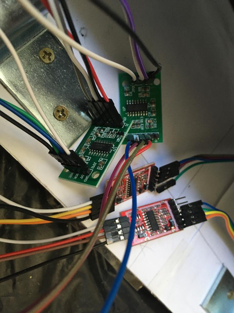
Red E+
Black E-
White A- (or B-)
Green A+ (or B+)

From the HX711, GND and VCC were connected to GND and 5V from the Arduino UNO. SCK and DT were connected to digital pin from 9 to 2.

I used this code to get the HX711/load cell readings

#include "HX711.h"

const int LC1_DOUT_PIN = 8;
const int LC1_SCK_PIN = 9;

const int LC2_DOUT_PIN = 6;
const int LC2_SCK_PIN = 7;

const int LC3_DOUT_PIN = 4;
const int LC3_SCK_PIN = 5;

const int LC4_DOUT_PIN = 2;
const int LC4_SCK_PIN = 3;


float calibration = 1;
float offset = 1;

HX711 balanca1;
HX711 balanca2;
HX711 balanca3;
HX711 balanca4;

unsigned long ult_tempo = 0;
unsigned long tempo = 0;

void setup() {
Serial.begin(38400);
Serial.println("Teste HX711");
Serial.println("Iniciando a balanca");
balanca1.begin(LC1_DOUT_PIN, LC1_SCK_PIN, 128);   
balanca1.set_scale (calibration);
balanca1.set_offset (offset);

balanca2.begin(LC2_DOUT_PIN, LC2_SCK_PIN, 128);  
balanca2.set_scale (calibration);
balanca2.set_offset (offset);

balanca3.begin(LC3_DOUT_PIN, LC3_SCK_PIN, 128);   
balanca3.set_scale (calibration);
balanca3.set_offset (offset);

balanca4.begin(LC4_DOUT_PIN, LC4_SCK_PIN, 32);  
balanca4.set_scale (calibration);
balanca4.set_offset (offset);
}

void loop() {
tempo = millis();
if(tempo - ult_tempo >= 2000){  
  Serial.print("balanca1: ");
  Serial.println(balanca1.get_units(10));
  Serial.print(balanca2.get_units(10));
  Serial.print(" balanca3: ");
  Serial.print(balanca3.get_units(10));
  Serial.print(" balanca4: ");
  Serial.println(balanca4.get_units(10));
 ult_tempo = tempo;
}

}

As indicated in some materials, I added and removed some known weights to do a calibration curve. Those materials (and a friend of mine that know some metrology basis) suggested to use the average of the electrical signal (in mV) from the load cells to construct the calibration curve.

The signal has increased when I put some weight and decreased when I removed them. In total, there were 5 loading and unloading cycles.Although, the signals that were read from HX711 had different magnitude, even three of them has amplified by 128x (cell 1, 2 and 3) and one by 32x (cell 4), as shown in the attached figure.

So I divided the signal from load cell 1 to 3 by 128 and load cell 4 for 32, taked their average and constructed the curve using the weight that I placed to the platform above the load cells.

Aparently it has a good fixing but I am not sure if the measured/amplified signals from HX711 are the mV multiplied to 128, 64 (for channel A) and 32 (channel B) or I need to do some other calculations to have the mV values from each load cell? And having those different magnitude from the same type of load cell is reasonable?

Many thanks for your attention.

calibration_curve.png

calibration_curve.png

Which Arduino, which HX711 board (some boards have a manufacturing fault, E- ground is missing).

Pictures/diagram and links please, according to the posting guidelines.

Do you know about the HX711-multi library?
Leo..

Hi. Thanks for replying! And sorry about the missing information. I had noticed that I forgot to explain the reason why I am trying to calibrate using loading and unloading cycles... Actually the scale I am trying to construct is part of a major project. And for now I am trying to verify if the load cells are within the parameters that the provider announced to use them in the project. So I tried to do a more laborious procedure to ensure some of the parameter that the provider announced (precision, hysteresis, absolute maximum error).

The Arduino I'm using is a generic Arduino UNO R3.

I used two cheaper HX711 board (green board from this provider) and two of this red model. I attached a photo of the HX711 boards. Two of the green HX711 would arrive this week, maybe I can test them replacing the red ones and see if there are differences. The way to verify if the E+ is grounded is measuring the E+ pin from HX711 board and GNG pin from Arduino? And I tried to measure the signals through A or B +- , but only get some results by measuring a signal pin from HX711 board and the ground pin from Arduino ( It was about 2,6V with a Hikari HM1001 multimeter.. not sure if it make sense as I read that the signal pins are half of the load cell output signal and the Arduino is providing <5V).

I don't know about the HX711-multi library, is it better to use the analog pin rather than the digital pin? I was intending to use a LCD with i2c to display the loads when necessary and the way I saw to connect the LCD is using two analog pin (and using four load cells there would be missing analog pin from Arduino UNO).

The library I used was HX711 library for Arduino. According the library's example, the function "get_units (10)" I used is to "average of 10 readings from the ADC minus tare weight, divided by the SCALE parameter set with set_scale". So I was intending to use the equation that I found from the calibration curve to determine the offset (tare) and calibration (scale) parameter. Maybe I should use 0 instead of 1 in offset, but it would only change 1 unit from the reading results.

So, I am supposing that the measured signals have a linear relation with the loading, but not sure if those measuring values are only the electrical signal (mV) from load cell amplified by the gain or there are other operations to consider while using HX711 to amplify the signal.

I tried to use the Fritzing to draw a diagram, but didn't found a load cell with 4 wires in the program, so sorry about my diagram.

And, again, many thanks for your attention and patience.

Some green boards have no ground plane on the back, which makes E- "floating", resulting in wrong excitation voltages and wrong/unstable weights.

Measure the voltage between E+ and E- (power/gnd to the load cell).
It should be almost exactly 4.25volt.

The HX711-multi library uses a shared clock signal, so only five wires for four HX711 boards.
Leo..

Wawa:
Some green boards have no ground plane on the back, which makes E- "floating", resulting in wrong excitation voltages and wrong/unstable weights.

Measure the voltage between E+ and E- (power/gnd to the load cell).
It should be almost exactly 4.25volt.

The HX711-multi library uses a shared clock signal, so only five wires for four HX711 boards.
Leo..

Hi! Thanks again. I measured the voltage between E+ and E- but I noticed that when I move the HX711 board (and the wires that connect HX711 to the load cell) the voltage changes... Then I remembered the recommendations about keeping the wire between the load cell and the HX711 short and twisted (which I haven't).
I will try to follow those recommendations and measure again. But, it seems that the voltage from the green HX711 are smaller than the red HX711. With a certain "movement" I measured a range from 3.4V to 3.9V from the green HX711 and from 3.8V to 4.0V. And when the wires are immobile, their variation were about 0.01V. And neither the green board nor the red board has achieved the 4.25V as you said...
I understand that the measured values are sensible to the entered voltage (Excitation voltage) which is provided from E+ an E- pin, as the load cell principle is to measure differences of voltage that are theoretically proportional to the resistance in the load cell (its strain gage's deformation/variation of resistance). But if I can unsure that the wires would be fixed during and after the calibration procedure, and the variation of E+ and E- voltage is still 0,01V, can I get reasonable measures from the load cell and HX711 board (maybe the red ones)? Or the excitation voltage must be near 4.25V... For what I am intending to measure, an maximum error/imprecision up to 150 g is still acceptable, but it would be better knowing the errors from the measurement.
If keeping the HX711 wire short, twisted and immobile works, in theory (from the load cell datashet), it has an output of 1.0 +-0.15 mV/V, so the variation of 0.1V would generate an variation of approximately 0.1mV from the load cell output? And from the calibration curve (if the measured values are the electrical signal in mV X gain and the new calibration curve has the same SCALE parameter of 0.0844) the error caused from the excitation voltage would be about 1.18g?
As I said, I am a newbie in electronic/ Arduino things... So please correct me if I am wrong.
Really appreciate your help. Thank you!

Better investigate that excitation voltage first.
~3.5volt is definitely wrong.

Also see this thread.
Leo..

This topic was automatically closed 120 days after the last reply. New replies are no longer allowed.