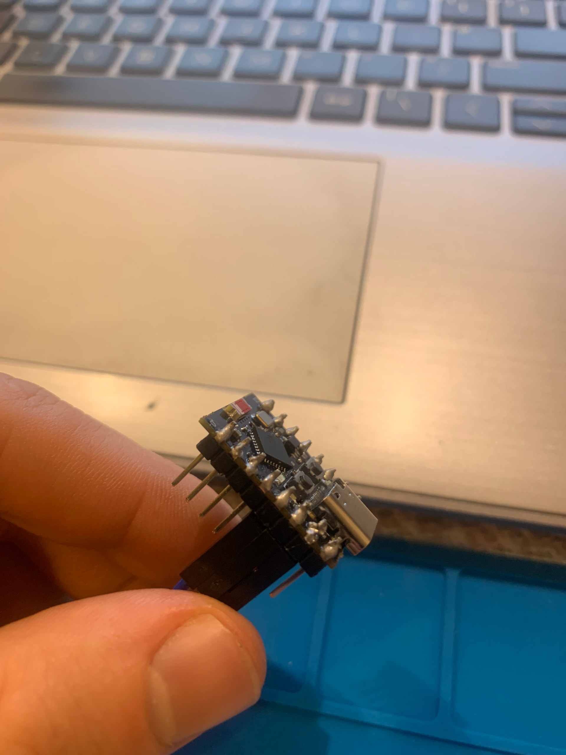
the following works OK on my ESP32C3 Supermini using GPIO5 SDA and GPIO4 SCL
// ESP32C3 Supermini SSD1306 OLED test using Adafruit_SSD1306 library

// program File>Examples?Adafruit_SSD1306>ssd1306_128x32_i2c

// NOTE: for Serial IO Enable USB CDC on Boot

/**************************************************************************
 This is an example for our Monochrome OLEDs based on SSD1306 drivers

 Pick one up today in the adafruit shop!
 ------> http://www.adafruit.com/category/63_98

 This example is for a 128x32 pixel display using I2C to communicate
 3 pins are required to interface (two I2C and one reset).

 Adafruit invests time and resources providing this open
 source code, please support Adafruit and open-source
 hardware by purchasing products from Adafruit!

 Written by Limor Fried/Ladyada for Adafruit Industries,
 with contributions from the open source community.
 BSD license, check license.txt for more information
 All text above, and the splash screen below must be
 included in any redistribution.
 **************************************************************************/

#include <SPI.h>
#include <Wire.h>
#include <Adafruit_GFX.h>
#include <Adafruit_SSD1306.h>

#define SCREEN_WIDTH 128  // OLED display width, in pixels
#define SCREEN_HEIGHT 32  // OLED display height, in pixels

// Declaration for an SSD1306 display connected to I2C (SDA, SCL pins)
// The pins for I2C are defined by the Wire-library.
// On an arduino UNO:       A4(SDA), A5(SCL)
// On an arduino MEGA 2560: 20(SDA), 21(SCL)
// On an arduino LEONARDO:   2(SDA),  3(SCL), ...
#define OLED_RESET -1        // Reset pin # (or -1 if sharing Arduino reset pin)
#define SCREEN_ADDRESS 0x3C  ///< See datasheet for Address; 0x3D for 128x64, 0x3C for 128x32
Adafruit_SSD1306 display(SCREEN_WIDTH, SCREEN_HEIGHT, &Wire, OLED_RESET);

#define NUMFLAKES 10  // Number of snowflakes in the animation example

#define LOGO_HEIGHT 16
#define LOGO_WIDTH 16
static const unsigned char PROGMEM logo_bmp[] = { 0b00000000, 0b11000000,
                                                  0b00000001, 0b11000000,
                                                  0b00000001, 0b11000000,
                                                  0b00000011, 0b11100000,
                                                  0b11110011, 0b11100000,
                                                  0b11111110, 0b11111000,
                                                  0b01111110, 0b11111111,
                                                  0b00110011, 0b10011111,
                                                  0b00011111, 0b11111100,
                                                  0b00001101, 0b01110000,
                                                  0b00011011, 0b10100000,
                                                  0b00111111, 0b11100000,
                                                  0b00111111, 0b11110000,
                                                  0b01111100, 0b11110000,
                                                  0b01110000, 0b01110000,
                                                  0b00000000, 0b00110000 };

void setup() {
  Serial.begin(115200);
  Serial.println();  // Wait for display
  delay(2000);
  // I2C - note GPIOs 8 and 9 don't work on ESP32C3 supermini - used for LED_BUILTIN and BOOT_BULILTIN
  Wire.begin(5, 4);  //(8, 9);// ESP32C3 setup I2C SDA and SCL
  // SSD1306_SWITCHCAPVCC = generate display voltage from 3.3V internally
  if (!display.begin(SSD1306_SWITCHCAPVCC, SCREEN_ADDRESS)) {
    Serial.println(F("SSD1306 allocation failed"));
    for (;;)
      ;  // Don't proceed, loop forever
  }
  Serial.println(F("SSD1306 allocation OK"));
  // Show initial display buffer contents on the screen --
  // the library initializes this with an Adafruit splash screen.
  display.display();
  delay(2000);  // Pause for 2 seconds

  // Clear the buffer
  display.clearDisplay();

  // Draw a single pixel in white
  display.drawPixel(10, 10, SSD1306_WHITE);

  // Show the display buffer on the screen. You MUST call display() after
  // drawing commands to make them visible on screen!
  display.display();
  delay(2000);
  // display.display() is NOT necessary after every single drawing command,
  // unless that's what you want...rather, you can batch up a bunch of
  // drawing operations and then update the screen all at once by calling
  // display.display(). These examples demonstrate both approaches...

  testdrawline();  // Draw many lines

  testdrawrect();  // Draw rectangles (outlines)

  testfillrect();  // Draw rectangles (filled)

  testdrawcircle();  // Draw circles (outlines)

  testfillcircle();  // Draw circles (filled)

  testdrawroundrect();  // Draw rounded rectangles (outlines)

  testfillroundrect();  // Draw rounded rectangles (filled)

  testdrawtriangle();  // Draw triangles (outlines)

  testfilltriangle();  // Draw triangles (filled)

  testdrawchar();  // Draw characters of the default font

  testdrawstyles();  // Draw 'stylized' characters

  testscrolltext();  // Draw scrolling text

  testdrawbitmap();  // Draw a small bitmap image

  // Invert and restore display, pausing in-between
  display.invertDisplay(true);
  delay(1000);
  display.invertDisplay(false);
  delay(1000);

  testanimate(logo_bmp, LOGO_WIDTH, LOGO_HEIGHT);  // Animate bitmaps
}

void loop() {
}

void testdrawline() {
  int16_t i;

  display.clearDisplay();  // Clear display buffer

  for (i = 0; i < display.width(); i += 4) {
    display.drawLine(0, 0, i, display.height() - 1, SSD1306_WHITE);
    display.display();  // Update screen with each newly-drawn line
    delay(1);
  }
  for (i = 0; i < display.height(); i += 4) {
    display.drawLine(0, 0, display.width() - 1, i, SSD1306_WHITE);
    display.display();
    delay(1);
  }
  delay(250);

  display.clearDisplay();

  for (i = 0; i < display.width(); i += 4) {
    display.drawLine(0, display.height() - 1, i, 0, SSD1306_WHITE);
    display.display();
    delay(1);
  }
  for (i = display.height() - 1; i >= 0; i -= 4) {
    display.drawLine(0, display.height() - 1, display.width() - 1, i, SSD1306_WHITE);
    display.display();
    delay(1);
  }
  delay(250);

  display.clearDisplay();

  for (i = display.width() - 1; i >= 0; i -= 4) {
    display.drawLine(display.width() - 1, display.height() - 1, i, 0, SSD1306_WHITE);
    display.display();
    delay(1);
  }
  for (i = display.height() - 1; i >= 0; i -= 4) {
    display.drawLine(display.width() - 1, display.height() - 1, 0, i, SSD1306_WHITE);
    display.display();
    delay(1);
  }
  delay(250);

  display.clearDisplay();

  for (i = 0; i < display.height(); i += 4) {
    display.drawLine(display.width() - 1, 0, 0, i, SSD1306_WHITE);
    display.display();
    delay(1);
  }
  for (i = 0; i < display.width(); i += 4) {
    display.drawLine(display.width() - 1, 0, i, display.height() - 1, SSD1306_WHITE);
    display.display();
    delay(1);
  }

  delay(2000);  // Pause for 2 seconds
}

void testdrawrect(void) {
  display.clearDisplay();

  for (int16_t i = 0; i < display.height() / 2; i += 2) {
    display.drawRect(i, i, display.width() - 2 * i, display.height() - 2 * i, SSD1306_WHITE);
    display.display();  // Update screen with each newly-drawn rectangle
    delay(1);
  }

  delay(2000);
}

void testfillrect(void) {
  display.clearDisplay();

  for (int16_t i = 0; i < display.height() / 2; i += 3) {
    // The INVERSE color is used so rectangles alternate white/black
    display.fillRect(i, i, display.width() - i * 2, display.height() - i * 2, SSD1306_INVERSE);
    display.display();  // Update screen with each newly-drawn rectangle
    delay(1);
  }

  delay(2000);
}

void testdrawcircle(void) {
  display.clearDisplay();

  for (int16_t i = 0; i < max(display.width(), display.height()) / 2; i += 2) {
    display.drawCircle(display.width() / 2, display.height() / 2, i, SSD1306_WHITE);
    display.display();
    delay(1);
  }

  delay(2000);
}

void testfillcircle(void) {
  display.clearDisplay();

  for (int16_t i = max(display.width(), display.height()) / 2; i > 0; i -= 3) {
    // The INVERSE color is used so circles alternate white/black
    display.fillCircle(display.width() / 2, display.height() / 2, i, SSD1306_INVERSE);
    display.display();  // Update screen with each newly-drawn circle
    delay(1);
  }

  delay(2000);
}

void testdrawroundrect(void) {
  display.clearDisplay();

  for (int16_t i = 0; i < display.height() / 2 - 2; i += 2) {
    display.drawRoundRect(i, i, display.width() - 2 * i, display.height() - 2 * i,
                          display.height() / 4, SSD1306_WHITE);
    display.display();
    delay(1);
  }

  delay(2000);
}

void testfillroundrect(void) {
  display.clearDisplay();

  for (int16_t i = 0; i < display.height() / 2 - 2; i += 2) {
    // The INVERSE color is used so round-rects alternate white/black
    display.fillRoundRect(i, i, display.width() - 2 * i, display.height() - 2 * i,
                          display.height() / 4, SSD1306_INVERSE);
    display.display();
    delay(1);
  }

  delay(2000);
}

void testdrawtriangle(void) {
  display.clearDisplay();

  for (int16_t i = 0; i < max(display.width(), display.height()) / 2; i += 5) {
    display.drawTriangle(
      display.width() / 2, display.height() / 2 - i,
      display.width() / 2 - i, display.height() / 2 + i,
      display.width() / 2 + i, display.height() / 2 + i, SSD1306_WHITE);
    display.display();
    delay(1);
  }

  delay(2000);
}

void testfilltriangle(void) {
  display.clearDisplay();

  for (int16_t i = max(display.width(), display.height()) / 2; i > 0; i -= 5) {
    // The INVERSE color is used so triangles alternate white/black
    display.fillTriangle(
      display.width() / 2, display.height() / 2 - i,
      display.width() / 2 - i, display.height() / 2 + i,
      display.width() / 2 + i, display.height() / 2 + i, SSD1306_INVERSE);
    display.display();
    delay(1);
  }

  delay(2000);
}

void testdrawchar(void) {
  display.clearDisplay();

  display.setTextSize(1);               // Normal 1:1 pixel scale
  display.setTextColor(SSD1306_WHITE);  // Draw white text
  display.setCursor(0, 0);              // Start at top-left corner
  display.cp437(true);                  // Use full 256 char 'Code Page 437' font

  // Not all the characters will fit on the display. This is normal.
  // Library will draw what it can and the rest will be clipped.
  for (int16_t i = 0; i < 256; i++) {
    if (i == '\n') display.write(' ');
    else display.write(i);
  }

  display.display();
  delay(2000);
}

void testdrawstyles(void) {
  display.clearDisplay();

  display.setTextSize(1);               // Normal 1:1 pixel scale
  display.setTextColor(SSD1306_WHITE);  // Draw white text
  display.setCursor(0, 0);              // Start at top-left corner
  display.println(F("Hello, world!"));

  display.setTextColor(SSD1306_BLACK, SSD1306_WHITE);  // Draw 'inverse' text
  display.println(3.141592);

  display.setTextSize(2);  // Draw 2X-scale text
  display.setTextColor(SSD1306_WHITE);
  display.print(F("0x"));
  display.println(0xDEADBEEF, HEX);

  display.display();
  delay(2000);
}

void testscrolltext(void) {
  display.clearDisplay();

  display.setTextSize(2);  // Draw 2X-scale text
  display.setTextColor(SSD1306_WHITE);
  display.setCursor(10, 0);
  display.println(F("scroll"));
  display.display();  // Show initial text
  delay(100);

  // Scroll in various directions, pausing in-between:
  display.startscrollright(0x00, 0x0F);
  delay(2000);
  display.stopscroll();
  delay(1000);
  display.startscrollleft(0x00, 0x0F);
  delay(2000);
  display.stopscroll();
  delay(1000);
  display.startscrolldiagright(0x00, 0x07);
  delay(2000);
  display.startscrolldiagleft(0x00, 0x07);
  delay(2000);
  display.stopscroll();
  delay(1000);
}

void testdrawbitmap(void) {
  display.clearDisplay();

  display.drawBitmap(
    (display.width() - LOGO_WIDTH) / 2,
    (display.height() - LOGO_HEIGHT) / 2,
    logo_bmp, LOGO_WIDTH, LOGO_HEIGHT, 1);
  display.display();
  delay(1000);
}

#define XPOS 0  // Indexes into the 'icons' array in function below
#define YPOS 1
#define DELTAY 2

void testanimate(const uint8_t *bitmap, uint8_t w, uint8_t h) {
  int8_t f, icons[NUMFLAKES][3];

  // Initialize 'snowflake' positions
  for (f = 0; f < NUMFLAKES; f++) {
    icons[f][XPOS] = random(1 - LOGO_WIDTH, display.width());
    icons[f][YPOS] = -LOGO_HEIGHT;
    icons[f][DELTAY] = random(1, 6);
    Serial.print(F("x: "));
    Serial.print(icons[f][XPOS], DEC);
    Serial.print(F(" y: "));
    Serial.print(icons[f][YPOS], DEC);
    Serial.print(F(" dy: "));
    Serial.println(icons[f][DELTAY], DEC);
  }

  for (;;) {                 // Loop forever...
    display.clearDisplay();  // Clear the display buffer

    // Draw each snowflake:
    for (f = 0; f < NUMFLAKES; f++) {
      display.drawBitmap(icons[f][XPOS], icons[f][YPOS], bitmap, w, h, SSD1306_WHITE);
    }

    display.display();  // Show the display buffer on the screen
    delay(200);         // Pause for 1/10 second

    // Then update coordinates of each flake...
    for (f = 0; f < NUMFLAKES; f++) {
      icons[f][YPOS] += icons[f][DELTAY];
      // If snowflake is off the bottom of the screen...
      if (icons[f][YPOS] >= display.height()) {
        // Reinitialize to a random position, just off the top
        icons[f][XPOS] = random(1 - LOGO_WIDTH, display.width());
        icons[f][YPOS] = -LOGO_HEIGHT;
        icons[f][DELTAY] = random(1, 6);
      }
    }
  }
}
serial monitor output
SSD1306 allocation OK
x: 31 y: -16 dy: 3
x: 31 y: -16 dy: 1
x: -1 y: -16 dy: 2
x: -14 y: -16 dy: 1
x: 110 y: -16 dy: 3
x: 87 y: -16 dy: 3
x: 66 y: -16 dy: 3
x: 119 y: -16 dy: 4
x: 99 y: -16 dy: 2
x: -9 y: -16 dy: 2
setup