Hello everyone,
as the title say (i hope i choose the right category) i fried my nano in a project and i can't understand what happened.
I was trying to control an old flip display clock, this clock require a 24v signal every minute to work, but this signal have to be inverted every time. I created a board with an arduino nano, a ds1307 rtc module, a L293D driver(so i can invert the polarities of the signal), an ir module to control the clock with a remote control and a 7805 to reduce the 24v to 5v for the arduino.
Everythink was working fine, i even soldered the components in a prototyping board and isolated the connection with hot glue. i have tested the board for several hours, nothing strange happened. Then i did the last think in my list to conclude the project, solder an header for the power supply. Before reconnecting the arduino i tested the voltage and everythink was fine. I reconnected the arduino and it was shorted between +5v and ground.
I don't know what happened, i pulled out the arduino and every component of the board looks good, on the other hand the arduino is still shorted even outside the board, i checked every pin with a magnifying glass and there is nothing stucked beetween the pins. I would appreciate if you can take a look at the board (i will upload a picture of the circuit) and give me and advice.
The clock is directly connected to the output of the L293D (pin 3 and 6), inside the clock there is a big coil that act as an elcetromagnet and control the mechanic.
This is my first post on the forum so i hope i i did everything correctly. Thanks everyone for reading.
Thanks for the reply, the upper positive line will carry the 24 volt to the l293d. It is also connected to the 7805 to reduce the voltage to 5v and go to the Arduino
If your voltage regulator outputs the 5v - why do you connect it to VIN Arduino pin? Vin input voltage must be above 6.5v, it cannot be supplied with 5v
Sorry but had to space it out into point from to read it.
Can you please post a copy of your circuit, in CAD or a picture of a hand drawn circuit in jpg, png?
Hand drawn and photographed is perfectly acceptable.
Please include ALL hardware, component names and pin labels.
Please not a Fritzy picture.
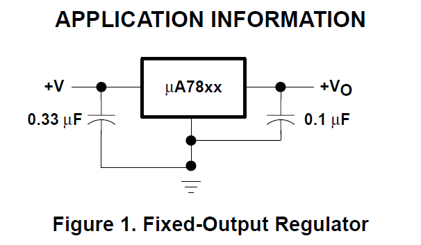
What value capacitors do you have around the 7805?
I see only one when the datasheet recommends;
yhea i know, in fact firstly i used an lm317 to output 6.6v, than i figured that this arduino worked preatty reliably even with 5v on the vin pin and i decided to use it to simplfy the board. I was using the vin pin and not the 5v rail because i was scared to damage the board, it happened anyway
thanks for the reply, i will draw a better schematic and upload it. About the capacitor i was using two 104 ceramic capacitor, they should be 0.1 µF, do you think they could be a problem? I see from your picture that i should have used a 0.33 µF for the input. About the power supply i would say it isn't the most reliable one, my 24v power supply is still being shipped so i figured I could have gotten away with two 12v power suplly connected in series, i tested the output with the multimeter and i got 24volt, the arduino was connected after the voltage regulator so i felt safe
Hi tom,
I measured the resistence between the 5vpin and the ground pin of the arduino(while it wasn't powered). I have tried to power on the arduino outside the board both from the usb and the vin pin (not simultaneously) before discoverying it was shorted, the power led was the only one turning on but very dimmed. The Arduino was out of the board... Is the circuit correct?
I figured 2 mistake about the l293d, first of all instead of connecting the 16th pin to the 24v (as i've done in the schematic) I've connected the 9th pin, my bad... Than i figured that the 16th pin have to be connected to 5v not to 24v. Strange it worked so long without giving trouble. Now i will fix the board and test it for some day. If everything work fine i ll close the post.
Thanks everyone
Edit: I tested the clock for a week and it has been working flowlessly. I read again the datasheet of the l293d and i found the while having 24 volt on the 16th pin wasn't a big problem 24v on 9th pin was way over the recomended voltage.