Can you show us your wiring. Not sure how. I am not strong on IBM type I fact I don't think I ever have put a picture on the web.
LarryD I am sorry but half of what I write is not posting. What happens if you place a wire from display pin 12 to ground? (a-g must have 470 ohm resistors. Nothing happens. No I do not know how to post pictures to the computer. I do not have your program. Not sure how it is to be import to my Arduino. I know a lot of I don't know.
tomorrow I will buy a bigger breadboard. this one is crowd. I believe that I have it wired correctly. When my grand daughter comes over I will have her take some pictures to post in the forum. now on to your program. I copy your program to the Arduino libraries. then what?
You download the library and the sample program from the link in post #5
http://learn.parallax.com/4-digit-7-segment-led-display-arduino-demo
Scroll to this image on the page:

Then review these to web links:
And
=============================================================
Have you confirmed the pin out of the display?
For segment a
+5v ----- 470 ------- segment a pin11 ------- cathode pin12 to ground (then 9,8,6)
For segment b
+5v ----- 470 ------- segment b pin7 ------- cathode pin12 to ground (then 9,8,6)
For segment c
+5v ----- 470 ------- segment c pin4 ------- cathode pin12 to ground (then 9,8,6)
For segment d
+5v ----- 470 ------- segment d pin2 ------- cathode pin12 to ground (then 9,8,6)
For segment e
+5v ----- 470 ------- segment e pin1 ------- cathode pin12 to ground (then 9,8,6)
For segment f
+5v ----- 470 ------- segment f pin10 ------- cathode pin12 to ground (then 9,8,6)
For segment g
+5v ----- 470 ------- segment g pin5 ------- cathode pin12 to ground (then 9,8,6)
To attach an image file (jpg), click "REPLY" then click "Attachments and other options" follow directions, example:

trying to load your program. Error message Reads:
The library "4-Digit-7Seg-LED-Display_Arduino-Demo" cannot be used. Library names must contain only basic letters and numbers. (ASCII only and no spaces, and it cannot start with a number)
Run Arduino, open Sketch, Open Include Library, Click on Add Zip Library, open folder download, highlight 4-Digit-7-Seg-LED-Arduino-Demo, click on open, receive above error message. I am using version 1.6.6
I copied my installation of the library.
See the attached ZIP file.
Download it, install this version, as directed in the links above.
When properly installed it should be in a directory similar to below:
C:\Users\YourName\Documents\Arduino\libraries\Multiplex7Seg
I have include the following example in the ZIP file it can be accessed from IDE/Examples :
#include <Multiplex7Seg.h>

byte digitPins[] = {9, 10, 11, 12};         // LSB to MSB
byte segmentPins[] = {2, 3, 4, 5, 6, 7, 8}; // Segment a to g
int counter;

void setup() {
  Multiplex7Seg::set(1, 4, digitPins, segmentPins);   // Initialize
  // See the example in Multiplex7Seg library for initialization parameters
}

void loop() {
  //Multiplex7Seg::loadValue(millis() / 10);  // Display incrementing value
  Multiplex7Seg::loadValue(counter++);  // Display incrementing value
  counter = counter % 10000; //at 10000 reset to zero

  delay(100);
}
Download the ZIP file below
.
Multiplex7Seg.zip (77.5 KB)
Close all your Arduino windows after installation.
Start the IDE up again.
The Multiplex7Seg will be recognized and you will see two examples offered to you when you select: File/Examples/Multiplex7Seg
Note:
Using a ULN2803 suggested in one of the posts above may not work as there is a saturation voltage of 1.2 volts on its outputs.
The 2N2222 transistors work well.
.
LarryD:
Note:
Using a ULN2803 suggested in one of the posts above may not work as there is a saturation voltage of 1.2 volts on its outputs.
It will work, but not well.
Not a good idea to use that series. If you must buy things, buy TPIC6B595s - the shift register version with a proper driver.
Saves you pins on the Arduino.
Paul__B:
It will work, but not well.Not a good idea to use that series. If you must buy things, buy TPIC6B595s - the shift register version with a proper driver.
Saves you pins on the Arduino.
ULN chips will work absolutely fine with displays like these. However, for displays with blue or white leds (very unlikely to be included in a starter kit), or for use on a 3.3V supply, the TPIC would be a better idea. But for red/yellow and most green displays, on a 5V supply, the higher sturation voltage does not matter, just lower your series resistors a little!
I only suggested ULN because it is 1) a component possibly included in a starter kit such as the OP has and 2) something you might be able to pick up at your local Radio Shack/Maplin. Neither is true of TPIC chips. But if you are buying on-line I agree it is the technically better choice, if not quite as simple for a beginner to get their head around.
ULN chips will work absolutely fine with displays like these.
I did say:
"may not"
![]()
Later on, the OP may want to try a MAX7219 and try SPI.
.
Finally got the program loaded. Now to go to work on the breadboard. bought a bigger breadboard. will try to lay it out so you can see how it is wired.
By the way. Thanks for hanging in there with me.
ran the program, no go. if I touch the pins with 5V the elements light up. I tried to attach picture but was told there to big. max 1 meg.

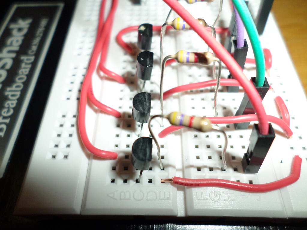
Nice and neat.
Might be nice to use different coloured wires to make things easier to follow.
Can you confirm the color on on the 470 resistors?
What is written on the transistors?
See image:

FYI:
http://www.buildcircuit.com/building-a-circuit-on-breadboard/
I assume there were no errors when you uploaded the sketch to the Arduino.
Are you using Multiplex7SegExample4Counter.ino ?
Please confirm the Yellow wire (GND) is indeed connected to ground.
.
OOPS is my face red. The yellow wire was wrong. PROBLEM. Only D segment is flashing on the last digit and solid on the other digits. Sometimes blinking on and off.


- What is the color of the 470 ohm resistors that are on segments a-g?
- Are you using Multiplex7SegExample4Counter.ino ?
- What is written on the transistors?
And:
Have you confirmed the pin out of the display?
For segment a
+5v ----- 470 ------- segment a pin11 ------- cathode pin12 to ground (then 9,8,6)
For segment b
+5v ----- 470 ------- segment b pin7 ------- cathode pin12 to ground (then 9,8,6)
For segment c
+5v ----- 470 ------- segment c pin4 ------- cathode pin12 to ground (then 9,8,6)
For segment d
+5v ----- 470 ------- segment d pin2 ------- cathode pin12 to ground (then 9,8,6)
For segment e
+5v ----- 470 ------- segment e pin1 ------- cathode pin12 to ground (then 9,8,6)
For segment f
+5v ----- 470 ------- segment f pin10 ------- cathode pin12 to ground (then 9,8,6)
For segment g
+5v ----- 470 ------- segment g pin5 ------- cathode pin12 to ground (then 9,8,6)