I need the Arduino code to control the rotation angle (setpoint or target angle) of a DC motor using encoder, Can you help me?

I want to make close loop negative feedback by using encoder to control rotation degree, which I can configure the desire point. For instance, if I configure the desire point or target angle at 80 degree in the terminal and upload the code to my Arduino Nano, the motor will move to 80 degree and if it is not at 80 degree the system will command the motor again and try to reach to 80 degree.

This is the link which is similar to what I want to do:
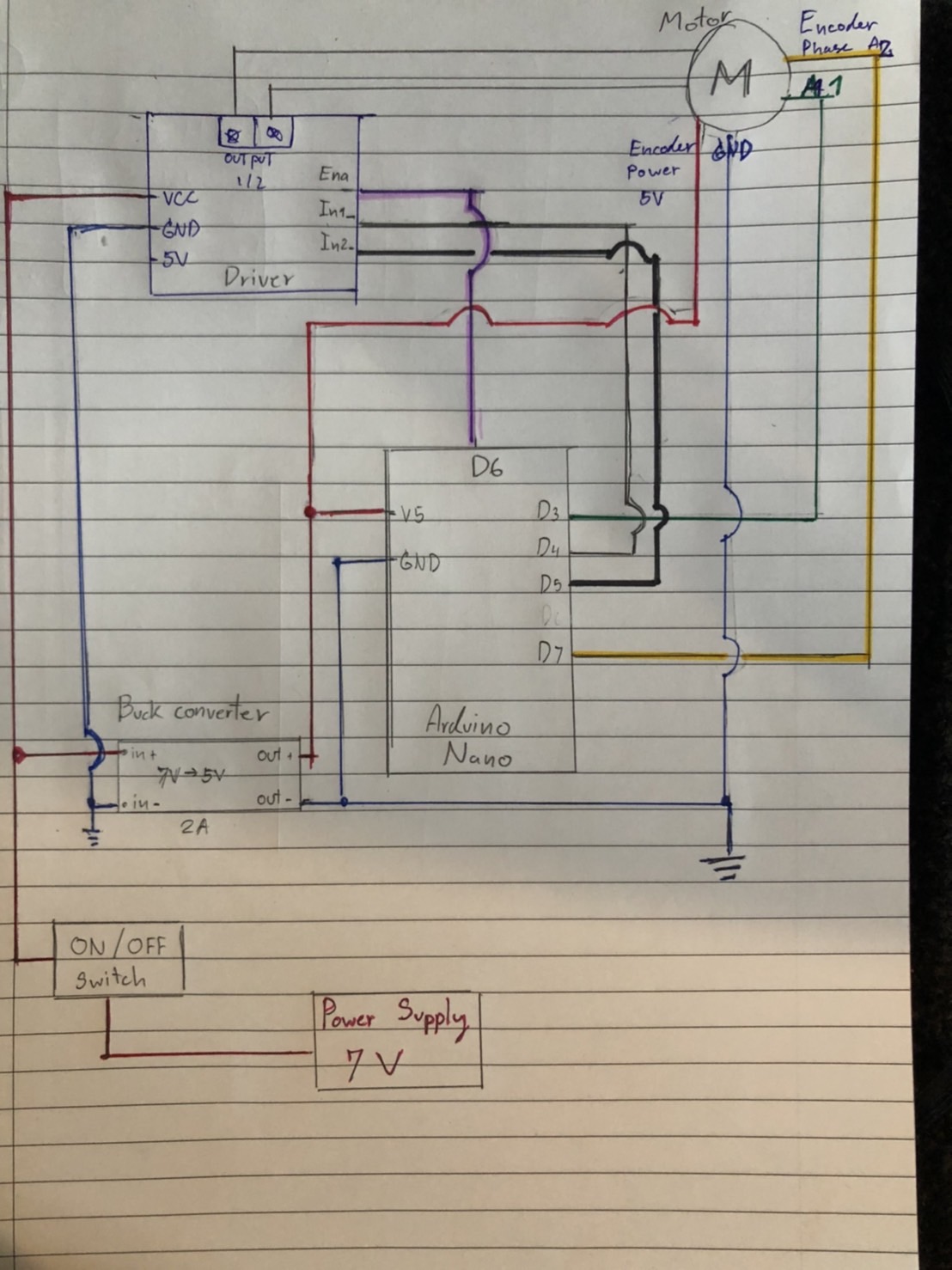
Motor detail:
Retarder Reduction Ratio 1:34
11 Pules / 1 Rev. or Hall x Ratio 34.02 = 341.2PPR

In addition, I am using L298H Driver to driver the motor.

I really need you guys a favor, I am a beginner and not sure how to this.


[code]
#define MotorA
int enA = 6;
int in1 = 4;
int in2 = 5;
int EncoderA1 = 3;
int EncoderA2 = 7;

//-----------//
int pos = 0;
long prevT = 0;
float eprev = 0;
float eintegral = 0;

void setup() {
  Serial.begin(9600);
  pinMode(in1, OUTPUT);
  pinMode(in2, OUTPUT);
  pinMode(enA, OUTPUT);

  pinMode(EncoderA1, INPUT);
  pinMode(EncoderA2, INPUT);
  attachInterrupt(digitalPinToInterrupt(EncoderA1), readencoder, RISING);

  Serial.println("target pos");
}

void loop() {

  //--------adjustable parameteer(Motor A)------------------------//
  int Target_Angle = 200;

  //--------PID Constants(Motor A)------------------------//
  float Kp = 1;   //proprtional constant
  float Ki = 0;   //intergral constant
  float Kd = 0;   //derivative constant

  float currentTime = millis();
  eprev = (currentTime - prevT) * 0.001; //dt

  // control signal
  float u = Kp * e + Kd * dedt + Ki * eintegral;

  // motor power//
  float pwr = fabs(u);
  if ( pwr > 255 ) {
    pwr = 255;
  }
  // motor direction//
  int dir = 1;
  if (u < 0) {
    dir = -1;
  }

  void readencoder() {
    int A2 = digitalRead(EncoderA2);
    if (A2 > 0) {
      pos++;
    }
    else {
      pos--;
    }
  }


[/code]

Please post the code You've got so far, and schematics.

That driver cannot handle the stall current of the motor (3 Amperes).

Otherwise, there are many tutorials on line. Search for "arduino motor control PID".

#define MotorA
int enA = 6;
int in1 = 4;
int in2 = 5;
int EncoderA1 = 3;
int EncoderA2 = 7;

//-----------//
int pos = 0;
long prevT = 0;
float eprev = 0;
float eintegral = 0;

void setup() {
Serial.begin(9600);
pinMode(in1, OUTPUT);
pinMode(in2, OUTPUT);
pinMode(enA, OUTPUT);

pinMode(EncoderA1, INPUT);
pinMode(EncoderA2, INPUT);
attachInterrupt(digitalPinToInterrupt(EncoderA1),readencoder,RISING);

Serial.println("target pos");
}

void loop() {

//--------adjustable parameteer(Motor A)------------------------//
int Target_Angle =200;

//--------PID Constants(Motor A)------------------------//
float Kp = 1; //proprtional constant
float Ki = 0; //intergral constant
float Kd = 0; //derivative constant

float currentTime = millis();
eprev = (currentTime - prevT)*0.001; //dt

// control signal
float u = Kpe + Kddedt + Ki*eintegral;

// motor power//
float pwr = fabs(u);
if( pwr > 255 ){
pwr = 255;
}
// motor direction//
int dir = 1;
if(u<0){
dir = -1;
}

void readencoder(){
int A2 = digitalRead(EncoderA2);
if(A2 > 0){
pos++;
}
else{
pos--;
}
}

Sorry about the code and the drawing schematics, they are a little bit messy and un clear

1 Like

what if I use Buck converter, will it help?

Use a motor driver that can handle the stall current. Pololu has the best selection.

Do NOT use the 5V Arduino output to power a motor. You can destroy the Arduino doing that.

Please edit your posts to add code tags.

1 Like

Sorry, how can I edit my post to add code tags

Select the code and use the "</>" editor button.

All this is described in the "How to get the best out of the forum" post, linked at the head of every forum category.

Quite well done.
Regarding the code: Please use the autoformat, Ctrl + T, in the IDE. Copy the code, click code tags, </>, in this window, and paste.
Regarding the schematics, I would like to see the power supply, voltage, Amps.... (Very often the power supply is inadekvat. )

Split the project into smaller parts.

  1. Make a test code for just running the motor. Note the remark from @jremington
  2. Add code reading the encoder.

This is wrong! millis() values must be kept in an unsigned long. The same must be used for all variables handling time, like float eprev = 0;

1 Like

Post the code again in Your next post, regarding the advice given.

1 Like

Hmmm.... this is interesting.
So, I'd would tell you a little bit of my background fist. I have very less experience in electronics, this subject is very new for me.

I have tested the circuit and it worked pretty well. I connected 2 motors (The motor) to L298N Dual H Bridge Stepper Motor Driver Board and the board used 7V from Power Supply machine, which Motor A connected to the 1 and 2 outputs, and the 3 and 4 outputs connected to Motor B.
The encoders which used 3.3V to 5V of both motor are powered another Power Supply, in this case, used 3.3V. The Signal of the encoder is detected by a scope machine.

However, I tested them without Arduino Nano.

So, could you please explain me a little bit about that? And if the driver cannot handle the stall current, how does it look like? e.g. it cannot rotate the motors or the driver will burn.

Thank you so much for your advice.

The link of the Driver:

so sorry, I want to make everything clearer to you but I am not sure how the make the schematics properly. I have no basis in electronic field, I am trying to learn about this.

I will use 7V to power L298N Dual H Bridge Stepper Motor Driver Board and the output 1 and 2 is connected to the motor and Arduino Nano will use 5V from the Buck converter which connects to Power Supply (7V). The Encoder A is connected to pin 3 and the Encoder B connects to pin 7, both encoders will power by the Buck converter as well. The In1 and 2 of the driver are connected to D5 and D6, the Ena (PWM signal) is connected to pin3.

Pen and paper works well most times.

This is a disaster. The more text the higher risk for misunderstandings. It gives no overview of the project. Pins here and pins there...... Useless information. That's the way the police works solving a murder, laying a jigg saw puzzle. No helper is fond of that.

1 Like

Do your own test. Stall the motor for some time, while applying full power, and see what happens.

The other problem with the ancient, inefficient L298 is that about half the battery power is lost to heat in the driver chip. Pololu has a good selection of modern motor drivers.

2 Likes

If you are free to choose what motor to use
take an RC-servo and you are done with 10 lines of code to turn the axle to the wanted position.

Or take a small stepper-motor which is also easier to code

The driver requires to be able to cope with the stall-current because you are doing feedback-loop positioning. This means the motor is accelerated clockwise and might overschoot a little bit which means the polarity is changed in the middle of the motor running clockwise and now immidiately shall run counter-clock-wise. In this situation the current goes up to the stall-current.

Be the change you want to see in the world
best regards Stefan

1 Like

what about theses motors (regular dc motor and 17 Nema), and I will use a potentiometer to read the angular position. Do you think they will work. Really need your advice, thank you.

I am sorry for that, and hopefully, this schematics drawing will give you more overview.

If I did anything wrong, please let me know.

If you are new to electronics and new to programming then you should use an RC-servo

An RC-servo unloads the burden of making the feedback-loop from physical position to wanted position to zero because an RC-servo has the feedback-loop working.

If the task is to just turn an indicator needle even the smallest servo is capable of that.

Limiting facctor: turning angle.

Which RC-servo you should use depends on the required turning angle.

Here is a cheap one. Though I don't know what turning angle it has

If it has to be from new zeeland

The other choice is a stepper-motor:

A steppermotor will need a "reference-switch" an one position to bring the stepper-motor into a defined position. Then you simply create the right amout of steps to rotate to the desired angle.

This is a small one that is often used in microcontroller projects.
It has a gear between motor-axle and connecting axle

if programming the negative-feedback-loop for positioning is a must there are two ways to do this:

a potentiometer on the axle that turns the indicator-needle
or what is shown in the video you have posted a rotary-encoder that is connected to the motor-shaft before the rpm-reducing gear. You will get a good positioning-precision only if the rotary-encoder is connected before the rpm-reducing gear

The example in the video you have posted has potentiometer.

The code you have posted is a simple copy & paste of the code posted in the videos comment.

As a general advice:
making such a project work is

much more work

than
"can somebody please post the cheat-code for entering platinum-level of game xy"

It is not done with copying & pasting some code - like pasting a cheatcode into an input-field.

You should give a pretty detailed description of why you are planning to build this project. It would be very good if you have some weeks of time to learn electronic basics and programming basics.

Be the change you want to see in the world
best regards Stefan

One question about the 5 volt fed to the controller. Does the schematic say: VS or is it the 5v pin? It needs to be the 5 volt pin.