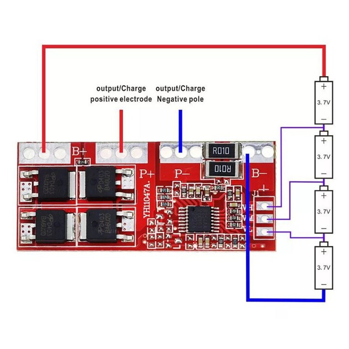
Power is supplied to P+, P- from the DC supply, and
The most negative part of the 18650 battery connected in series is connected to B-, and the most positive part of the 18650 battery connected in series goes to B+.
I have two voltage sensor configurations in mind. Is one of them correct? Or are they both wrong?
The voltage sensor is configured with the voltage sensor in the link below.
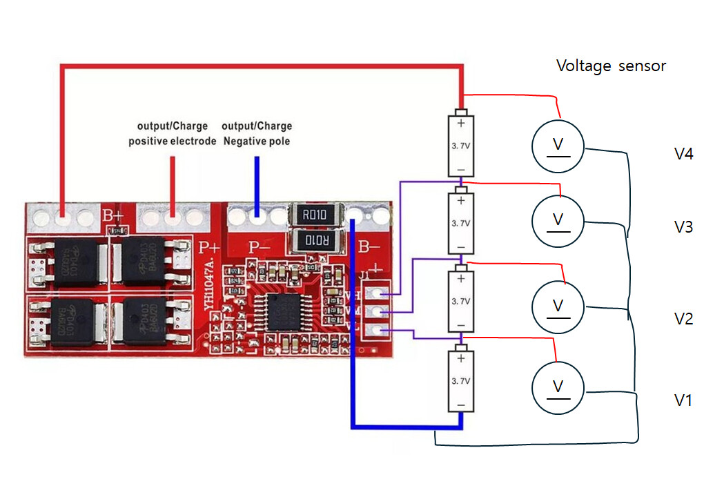
Method 1.
Connect all GND of the voltage sensor to the B- side and connect each VCC to the + side of each 18650 battery.
I had a problem when I connected it to the 2nd line. The wire suddenly turned almost 50 degrees, so I thought something was wrong and immediately disconnected it.
If I want to measure the voltage of each battery, which method should I use, 1 or 2?
Or is there another way?
I want to record how the voltage changes each second. I have a multimeter, but it doesn't connect to the computer, so I don't know which method would be best.
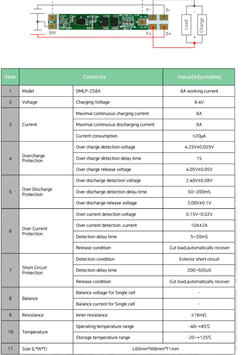
That is NOT a BMS, it's just a charger board. I see no high temp, low temp, over/under voltage, over current, short circuit protection and where is the shut off relay(solid state)?
The BMS diagram I showed you was a picture I found to show you an example of the connection.
The BMS I used are these two types.
Does this model's BMS also have this function?
I used the BMS because I wanted to observe cell balancing.
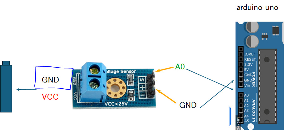
I can't find a voltage sensor that I can use with Arduino, perhaps because my search skills are lacking.
Is there any model that can measure voltage?
Can I only measure voltage with an analog pin within the 0~5V range of Arduino?
Even though the voltage resolution is somewhat low, I wanted to see the trend first.
When I bought it, it said it was a sensor on the page, so I bought it.
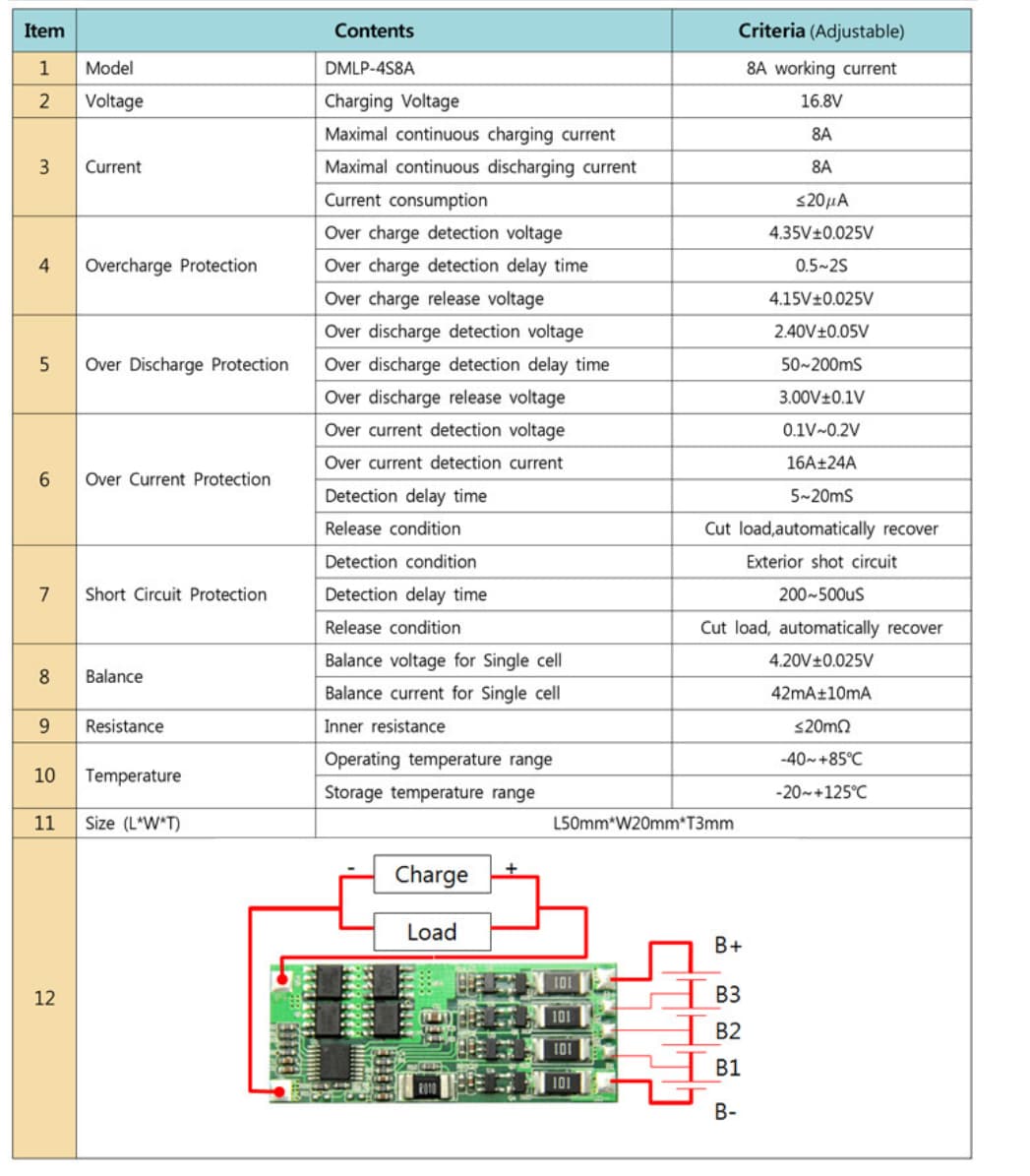
I think the problem is that the BMS photo I used as an example is not of the model I am using.
I have attached a picture and specs of the BMS I am using. Does this model appear to have cell balancing? What parts of the circuit should I check to see if it does the desired function?
You may not see anything. A BMS can make very small changes to the charge current on each battery in order to make things "Balance" but there is no harm in looking.
I am not sure what you are driving at. As a thought exercise ONLY, drop a steel screwdriver across the battery + and battery -. Does the battery shut down with no ill affects? If the answer is yes then it's most likely a BMS, if the answer is NO then it is 100% NOT a BMS.
Another test is to take the temperature lead from the BMS and immerse it in a glass of water with melting ice cubes. Again, the battery should disconnect. Of course if there is NO temperature lead, then it is 100% sure NOT a BMS.
There are NO English language google hits for that device. DMLP-4S8A but the spec sheet appears to have all the specs (but 1) for a BMS. What I do not see is the temperature probe that attaches to the battery itself as Lithium cells have specific to chemistry values that cause explosions (hot) or battery destruction (cold)
Cell balancing is just one function of a BMS and is actually the least important function.
Is this 'BMS' going to be permanently attached to the batteries?
The first one you show does do cell balancing, the second apparently does not.
What parts of the circuit should I check to see if it does the desired function?
For the balance function, you need to accurately measure the voltage of each cell. If at the end of charge each battery is 4.20V +/-25mV then the balancing worked.
What I wanted to see was how the voltage of each battery changes when the BMS's cell balancing function is activated.
I wanted to check how the BMS's cell balancing function works, and I wanted to try my own cell balancing experiment with active or passive cell balancing functions.
I think the battery I used is a shenzhen longyan sheng 18650 battery.
I couldn't find the exact sales link, but this is the 18650 picture.
That's what your "sensor" does. Lowering with voltage divider the battery voltage to level that arduino ADC can sense.
The question is, do you really need them? Your BMS should take care of the balancing.
There are few negative aspects using them, like small extra battery drain and potentially harmful current draw through arduino analog pin if you disconnect VCC from arduino.
Edit: If the purpose is just experimental, go on. I have doubts you "see" a lot if your BMS is working like expexted.