i2c appears to not be reading anything.

So I thought this would be very easy but it isn't working for me!

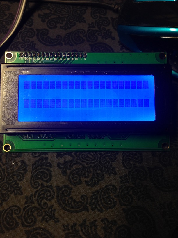
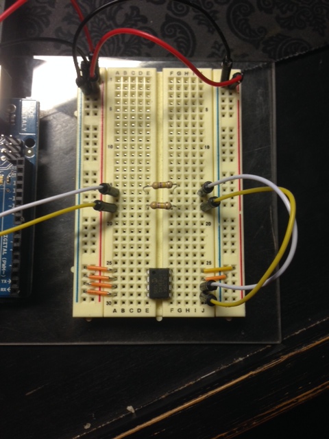
Very simple LCD with backpack purchased off of Ebay and 24lc256 EEPROM chips hooked up to the i2c bus and whats interesting is the scanner(s) I have tried doesn't find anything.

I uploaded another random sketch like the blink to verify the ATMEGA328 is ok and it was so I am at a loss and I have a feeling it is not the Arduino Uno's fault.

LCD / UNO
GND -> GND
+5VDC -> VCC
SDA -> A4
SCL -> A5

Scanner sketches used:

#include <Wire.h>

void setup()
{
  Serial.begin(9600);
  Wire.begin();
  
  byte Return;
  
  Serial.println("Scanning I2C bus...");
  for(byte I2CAddress = 1; I2CAddress <= 127; I2CAddress++)
  {
    Serial.print("0x");
    if (I2CAddress<16)
      Serial.print("0");
    Serial.print(I2CAddress, HEX);
    Serial.print(" (");
    if (I2CAddress<10)
      Serial.print("  ");
    else if (I2CAddress<100)
      Serial.print(" ");
    Serial.print(I2CAddress);
    Serial.print("): ");
    
    Wire.beginTransmission(I2CAddress);
    Return = Wire.endTransmission();
    
    if (Return == 0)
      Serial.print("OK!");
    else
      Serial.print("   ");
      
    if (I2CAddress % 5)
      Serial.print("    ");
    else
      Serial.println();
  }
}

void loop() { }
// I2C Scanner
// Written by Nick Gammon
// Date: 20th April 2011

#include <Wire.h>

void setup() {
  Serial.begin (115200);

  // Leonardo: wait for serial port to connect
  while (!Serial) 
    {
    }

  Serial.println ();
  Serial.println ("I2C scanner. Scanning ...");
  byte count = 0;
  
  Wire.begin();
  for (byte i = 8; i < 120; i++)
  {
    Wire.beginTransmission (i);
    if (Wire.endTransmission () == 0)
      {
      Serial.print ("Found address: ");
      Serial.print (i, DEC);
      Serial.print (" (0x");
      Serial.print (i, HEX);
      Serial.println (")");
      count++;
      delay (1);  // maybe unneeded?
      } // end of good response
  } // end of for loop
  Serial.println ("Done.");
  Serial.print ("Found ");
  Serial.print (count, DEC);
  Serial.println (" device(s).");
}  // end of setup

void loop() {}
// --------------------------------------
// i2c_scanner
//
// Version 1
//    This program (or code that looks like it)
//    can be found in many places.
//    For example on the Arduino.cc forum.
//    The original author is not know.
// Version 2, Juni 2012, Using Arduino 1.0.1
//     Adapted to be as simple as possible by Arduino.cc user Krodal
// Version 3, Feb 26  2013
//    V3 by louarnold
// Version 4, March 3, 2013, Using Arduino 1.0.3
//    by Arduino.cc user Krodal.
//    Changes by louarnold removed.
//    Scanning addresses changed from 0...127 to 1...119,
//    according to the i2c scanner by Nick Gammon
//    http://www.gammon.com.au/forum/?id=10896
// Version 5, March 28, 2013
//    As version 4, but address scans now to 127.
//    A sensor seems to use address 120.
// 
//
// This sketch tests the standard 7-bit addresses
// Devices with higher bit address might not be seen properly.
//

#include <Wire.h>


void setup()
{
  Wire.begin();

  Serial.begin(9600);
  Serial.println("\nI2C Scanner");
}


void loop()
{
  byte error, address;
  int nDevices;

  Serial.println("Scanning...");

  nDevices = 0;
  for(address = 1; address < 127; address++ ) 
  {
    // The i2c_scanner uses the return value of
    // the Write.endTransmisstion to see if
    // a device did acknowledge to the address.
    Wire.beginTransmission(address);
    error = Wire.endTransmission();

    if (error == 0)
    {
      Serial.print("I2C device found at address 0x");
      if (address<16) 
        Serial.print("0");
      Serial.print(address,HEX);
      Serial.println("  !");

      nDevices++;
    }
    else if (error==4) 
    {
      Serial.print("Unknow error at address 0x");
      if (address<16) 
        Serial.print("0");
      Serial.println(address,HEX);
    }    
  }
  if (nDevices == 0)
    Serial.println("No I2C devices found\n");
  else
    Serial.println("done\n");

  delay(5000);           // wait 5 seconds for next scan
}

Do you have the required pull-up resistors on SCL and SDA?

John,

No I don't, I was under the impression the Arduino did that (automatically or something). Whats a recommended size?

Placed I tried 47k, 39k and 10k with no change...

A typical value would be 4.7K but that depends on the I2C bus speed.In general a 4.7K should do the job.
What I2C chip does your board have?
On the photo it appears to be an mcp
The address of the chip is normally done connecting some pins to ground or VCC. You could check on your board what is the address checking those pins according to the datasheet.
Even that the I2C scanner should find it .

Ok I completely reset, grabbed a new breadboard and all new wires and tested just the (different from yesterday aka new chip) eeprom chip and tested the LCD separate with both failing to read on the scanner.

Resistor's:

4.7k Ohm

Wires are:

Orange = GND's
Yellow(on eeprom) = +5Vdc
White = SCL
Yellow = SDA
Red = +5Vdc
Black = GND

I am thinking there is something I am screwing up consistently OR I have a hardware issue.

Can I manually jumper the LCD backpack if needed for a set address?

Lance

Your resistors appear to be in series on the SCL and SDA lines. To pull those lines up the resistors need to be from SDA and SCL pins to Vcc.

Ah dumb me... but still nothing once corrected.

Hi there

Sorry, this is a REALLY dumb question, so shoot me down if I'm wrong.

You have power feeding into the red and blue verticals on the left side of your breadboard. Are those connected internally to the red and blue verticals on the right hand side? If not, there is no power getting to the IC.

If there is, I should know better :slight_smile:

All the best

Ray

OMG..... Ok I swear I haven't done this many dumb things in a row before! :fearful: but unfortunately no change!

Double check you don't have SDA and SCL round the wrong way.

At the Arduino: A4 (SDA), A5 (SCL)

On the EEPROM: 5 (SDA), 6 (SCL).

Hack, checks out right. So weird..... Any other checks?

Write a small sketch to check the A4 and A5 pins to make sure they didn't, somehow, get toasted? Set them as digital inputs and wire up a couple of switches, or outputs and blink a LED.

Hack, checks out right. So weird..... Any other checks?

Did you change things after taking the photos that were in post #5 and #7? It looks like a yellow jumper goes from A5 to row 18 of the breadboard. Then another yellow jumper goes to EEPROM pin 5.

Tested A4/A5 with blink and LED. Perfect.

Picture of current setup.

That is very strange to happen, but it would be very cool to track that problem. :grin:
Grab a multimeter and use connectivity test and check all your wires.One common problem sometimes happen, is some breadboards are cute in the middle in the power rail lines.From the picture you post it doesn't seem your breadboard have that problem since the red trace and blue trance are note cute, but test it to make sure.
Also check if the 5V are in the eeprom pins 4(GND) and 8 (VCC).

Ok tested as follows:

Checked power rails on both sides and they run the length of the breadboard.

Checked each wire for breaks. None found.

Checked for power at EEPROM Pin 8 VCC - +4.88Vdc
Pins 1-4 and 7 all 0Vdc as expected due to being on ground.
Pin 5 expected +5Vdc read +4.80Vdc
Pin 6 expected (unsure) read 0Vdc

Thoughts?

Ok I have an update. I pulled out my nifty shield to burn a new bootloader on a brand new atmega328 and swapped it out and everything works. $)

I swear this craps a PITA!

Next I will re-burn the bootloader on the original chip and see if it will now work.

Result - The original atmega328 DID NOT work after a fresh bootloader install.

Hi,

I have a very similar problem. Can you one more time confirm that the original Atmega328 chip (which was preinstalled on the board) was unable to work with i2c ? So that means that cheap china clones do not have a 100% functional inside?