I am using an Uno R3 with a 1602 LCD module. When connected to 5V, gnd, scl, and sda, the display lights up but is stuck on scanning when using both the Wire>i2c_scanner and when using the hd44780>I2CexpDiag.
I then connected the display to an Arduino Pro and it worked perfectly. I unfortunately need to use the Uno R3 for this project. Does anyone have any ideas what could be going on?
Reported Arduino Revision: 1.6.7
CPU ARCH: AVR - F_CPU: 16000000
SDA digital pin: 18 A4
SCL digital pin: 19 A5
Checking for required external I2C pull-up on SDA - YES
Checking for required external I2C pull-up on SCL - YES
Checking for I2C pins shorted together - Not Shorted
Actually, the Uno does have pullups - the pullups that are built into the AVR on those pins. The Wire library enables them.
Yes they are very weak and are way outside of spec but they typically work enough for a simple scenario of a single i2c LCD device on relatively short wires.
And also, most of the i2c PCF8574 based LCD backpacks have pullups on the i2c backpack which are strong enough to meet the i2c spec requirements.
That said,
I2CexpDiag checks for external pullups - it tests the pins before it does a scan.
It reported seeing external pullups which should mean that it is seeing the pullups on the i2c backpack.
@nikkileemar
I'm curious on this as I've never seen an i2c address scan lock up on an AVR.
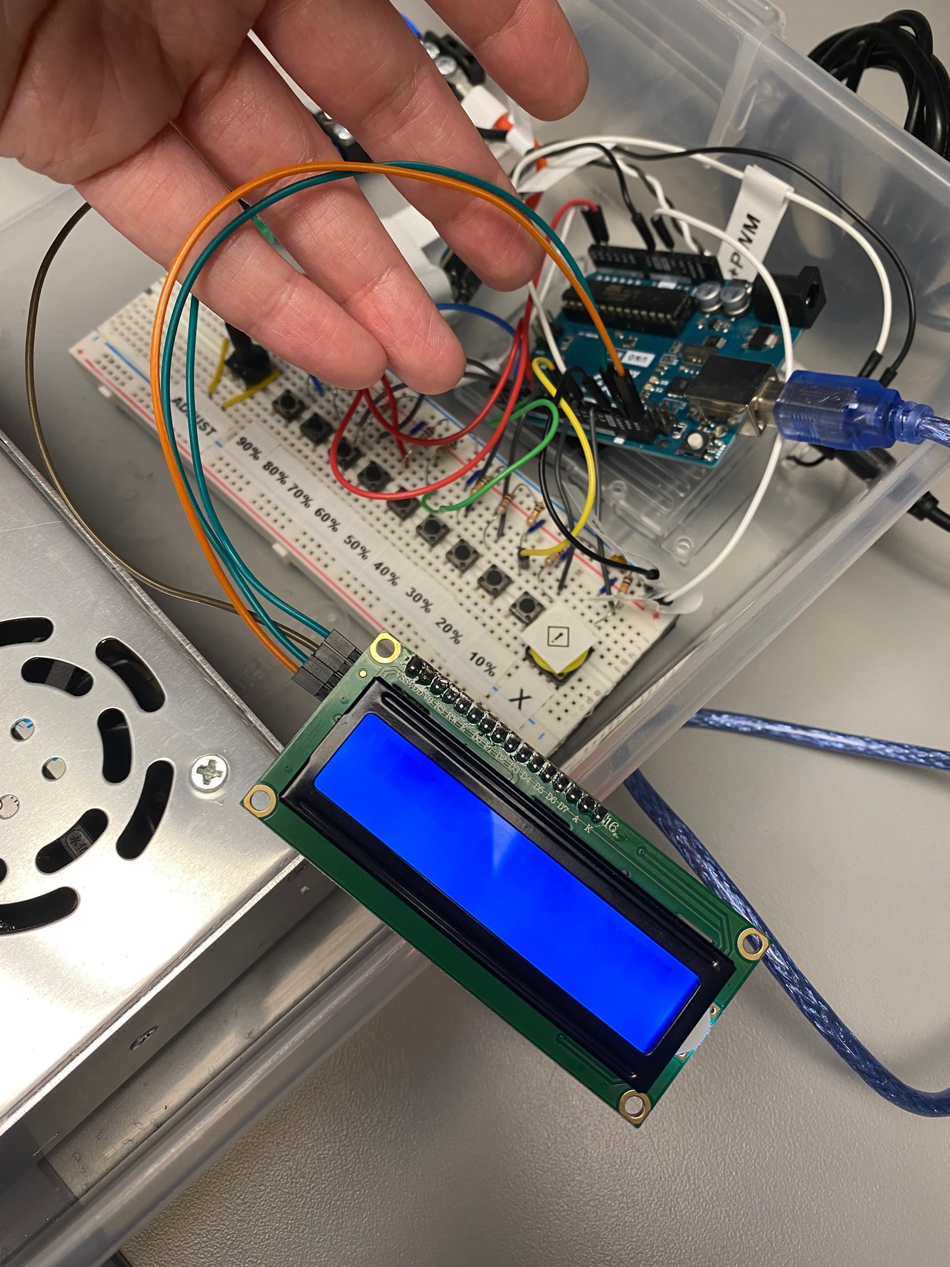
Can you post some photos of your wiring and your LCD device so we can see what you are using, how it is powered , the i2c wires to the LCD, the LCD backpack, and the soldering of the modules.
I'd be curious if it still locks up when you disconnect the LCD and the wires going to the UNO.
Try adding some pull up resistors in teh 4.7K range to SCA and SDA, I believe your problems will go away. If that fails and the software works you possibly have a bad part. The display being light is probably a matter of chance and circuit board design. All of the ones I have light up until I turn them off with software. If I just power them they light up without any other connections.
Interestingly, neither does the Arduino Pro which the OP says he has tested successfully. The Arduino Pro mini, however, may have these depending on the exact clone.
It does not make sense to add pullup resistors to ADC pins by default. That's why the Uno and all boards with the same controller don't have pullup resistors on A4/A5.
The software test for pullup resistors is a fake, it can not determine the resistance of eventual pullups.
SCL digital pin: 19 A5
--------------------------------------------------------------------
Checking for required external I2C pull-up on SDA - YES
Checking for required external I2C pull-up on SCL - YES
Checking for I2C pins shorted together - Not Shorted
--------------------------------------------------------------------
Scanning i2c bus for devices..
 i2c device found at address 0x27
Total I2C devices found: 1
--------------------------------------------------------------------
Scanning i2c bus for all lcd displays (4 max)
 LCD at address: 0x27 | config: P01245673H | R/W control: Yes
Total LCD devices found: 1
--------------------------------------------------------------------
LCD Display Memory Test
Display: 0
 Walking 1s data test:	PASSED
 Address line test:	PASSED
--------------------------------------------------------------------
Each working display should have its backlight on
and be displaying its #, address, and config information
If all pixels are on, or no pixels are showing, but backlight is on, try adjusting contrast pot
If backlight is off, wait for next test
--------------------------------------------------------------------
Blinking backlight test: to verify BL level autodetection
If backlight is mostly off but
you briefly see "BL Off" on display with backlight on,
then the library autodetected incorrect BL level
and the library cannot autoconfigure the device
--------------------------------------------------------------------
Displaying 'uptime' on all displays
In the Uno picture you appear to have the LCD connected to SDA and SCL but you also appear to have something connected to A4 and A5 which are effectively the same (I2C) pins. Try removing the connections to A4 and A5 and see if it is any better.
I assure you. The pullup presence test in I2CexpDiag is not fake. It can reliably detect the presence of external resistors on the i2c signal pins.
Sure, it cannot detect the resistance of the pullups but it can reliably detect that external pullups are attached which is what is important.
Don't believe me, then hook up an Arduino board, and run some tests using I2CexpDiag and see what results you get when external pullups are present vs not present.
The i2c backpack you are using has pullups on it.
There is no need to add any additional pullups.
If you look a the 2CexpDiag output, it reported that it detected the pullups.
You were correct. There was one wire in the A4 pin, and once removed it worked. The wire that was in A4 connects to a potentiometer. Do you know if there is a way to allow both the potentiometer and the LCD to work in this setup? Or is it only possible to have one connection at a time to the I2C pins?
@bperrybap You are correct - pull-up resistors were not necessary to add.
That's one of the problems which the pullup test can not detect. If the pot is set near GND then "no pullup" would erroneously be detected. Relying on such unsafe diagnostics can cause wrong remedy attempts or damage when interpreted without better knowledge.
if there was a pot attached to an i2c signal and turned so that it was driving the voltage to near ground or even if shorted to ground, the diag test would have reported that the signal was "STUCK LOW" with no potential for any h/w damage.
Whenever things are electrically connected improperly there can be damage.
That is always a risk when playing at this level.
There is no way to protect users from themselves in this respect.
The tests that I2CexpDiag does do not do anything to the pins that the Wire library would not do during its operation.
I2CexpDiag goes to great lengths to avoid doing anything that could cause electrical damage by doing things with the internal pullups as much as possible to avoid any potential for damage including for situations where things are not connected properly.
The only thing that might cause damage is if the i2c pins were directly shorted to VCC.
But then if that were the case, then just using the Wire library would have the same issue as the Wire protocol requires that the master drive the signals low.
If the pins were shorted to VCC then the MCU could experience damage whenever it attempted to drive the pin ouput to ground given there would be an infinite short.
And again, I2CexpDiag is a tool. It is used to help diagnose issues.
Yes there are cases that it cannot diagnose.
But, in the real world, it will identify most of the issues that users tend to have.