Hi!
I'm having an issue where the i2c communication doesn't work properly. The goal is to have this communication work without having arduinos to be connected via USB cables to the arduinos.
Systems:
-Udoo x86 II
-Arduino Uno (x4)
-Converters from 24V to 10V.
I have this set up: SLC SDA are connected to pins 16 and 17. Labelled in the arduinos.
The udoo works as a master and the arduinos as slaves.
The programs I'm using are the following:
MASTER:
#include <Wire.h>

const int16_t SLAVE1 = 0x01; //Hexadecimal Directions for slaves.
const int16_t SLAVE2 = 0x02;
const int16_t SLAVE3 = 0x03;
const int16_t SLAVE4 = 0x04;
//...

void setup() {
  Wire.begin();  // join i2c bus no address = master
  Serial.begin(9600);
}

byte x = 0;

void loop() {

  Serial.println("Transmiting to Slave1");
  Wire.beginTransmission(SLAVE1);  // transmit to slave1
  Wire.write("x is ");                // sends five bytes
  Wire.write(x);                      // sends one byte
  Wire.endTransmission();             // stop transmitting

  delay(500);

  Serial.println("Transmiting to Slave2");

  Wire.beginTransmission(SLAVE2);  //transmit to slave2
  Wire.write("x is ");
  Wire.write(x);
  Wire.endTransmission();

  delay(500);

  Serial.println("Transmit to Slave3");

  Wire.beginTransmission(SLAVE3);  // transmit to slave3
  Wire.write("x is ");                // sends five bytes
  Wire.write(x);                      // sends one byte
  Wire.endTransmission();             // stop transmitting

  delay(500);
  Serial.println("Transmit to Slave4");

  Wire.beginTransmission(SLAVE4);
  Wire.write("x is ");
  Wire.write(x);
  Wire.endTransmission();

  delay(500);


 x++;
}
SLAVES
#include <Wire.h>


const int16_t Slave1= 0x01; // adress

void setup() {
  Serial.begin(9600);  // start serial for output
  Wire.begin(Slave1);  // new syntax: join i2c bus (address required for slave)
  Wire.onReceive(receiveEvent);             // register event
}

void loop() {}

// function that executes whenever data is received from master
// this function is registered as an event, see setup()
void receiveEvent(size_t howMany) {

  (void)howMany;
  while (1 < Wire.available()) {  // loop through all but the last
    char c = Wire.read();         // receive byte as a character
    Serial.print(c);              // print the character
  }
  int x = Wire.read();  // receive byte as an integer
  Serial.println(x);    // print the integer
}

void requestEvent() {
  byte a = 1;
  Wire.write(a);

}
Each slave has the same program with differend adress and requestEvent writes 2 3 and 4.
I upload each program into the arduinos. Then the master program.
The slaves correctly recieve values from the master " x is : 1 , x is: 2 ...."
The master doesn't recieve the values from the slaves properly. it prints 0 , 0 , 0 , 0.
I've had this working before. Everything started going worse when I tried to try the system without the usb connections pluged in.
If In the middle of the execution of the program if I unplug the USB's of the arduinost he execution of the Master Serial freezes , I can't load programs into the arduino and I need to restart the computer.
I've checked the continuity of the I2C lines and they are correct. I don't know why this is happening and I need some help please.
Just for the pedants:- if a connection is supplied by an optical isolated input, you make your own common referance point on the output side of the opto isolator.
Not sure about if they are isolated. I'll give a try and get back to you. Thank you for the help.
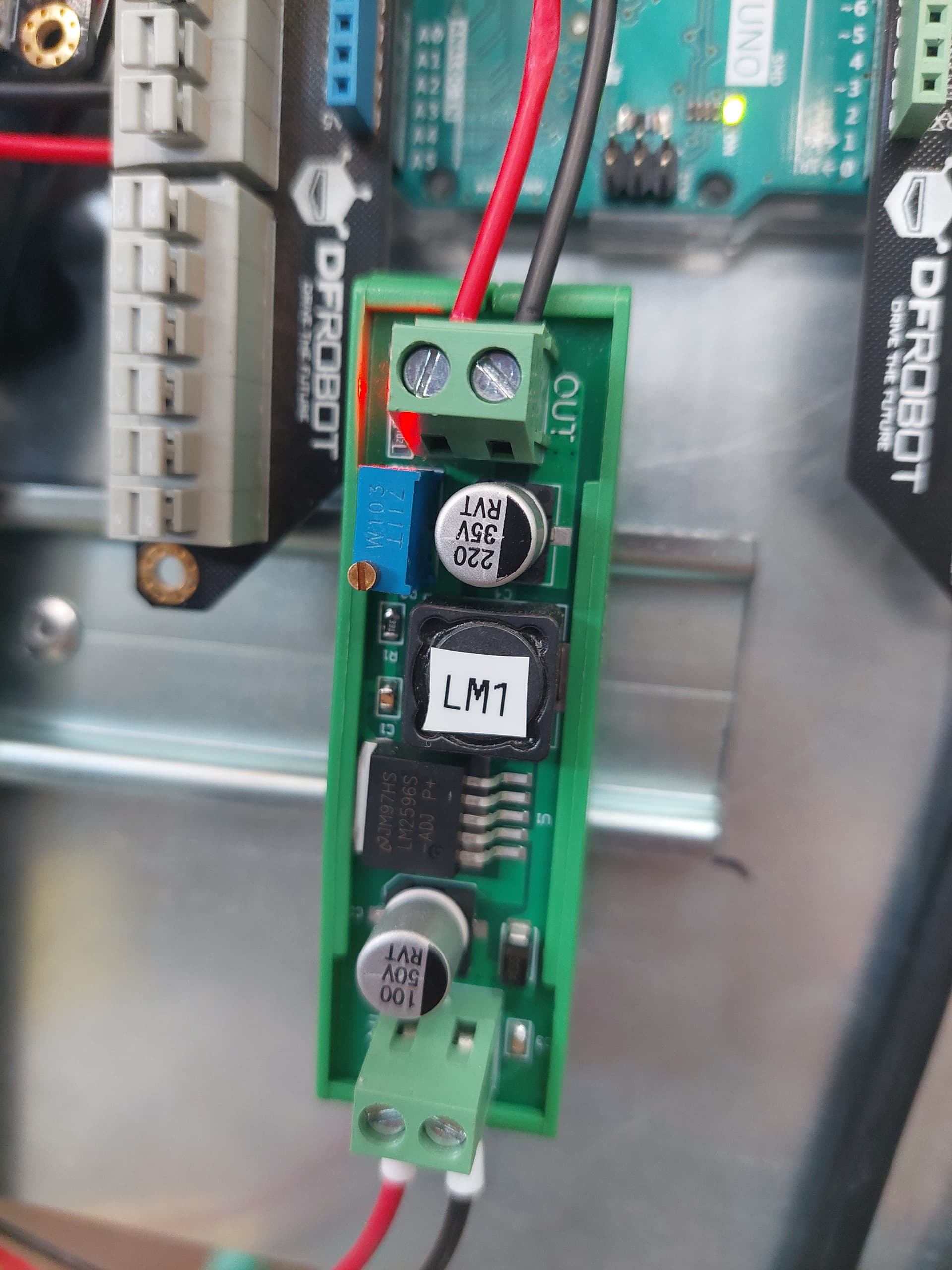
These are the converters I'm using: I have no idea if they have any documentation or how to find it.
They are unlikely to be isolated. Just check with a resistance meter if the ground on the output is connected to the ground of the input. With all power off.
That's not the trouble maker. All signal GNDs have to be connected to the I2C bus, including the Arduinos and the Udoo. Assumptions about hidden connections in other places are dangerous because, if they exist, can inject any kind of noise, form ground loops etc..
Why do you need a separate PSU for each Arduino? Why 10V?
The goal is to have the Udoo recieve serial data from somewhere else, decide which slave to send it and then send it. This program was a debugging tool to check if everything worked properly. I didin't understand why it wasn't working when I changed the USB connections into an external power supply for the arduinos. @Grumpy_Mikelink was very helpful to understand what was the problem.