I2C LCD 4x20 woes with mystery characters

I have had untold grief from getting my 4x20 to work. It was fine a couple of years ago but, now that I have gone back to it, I guess I must have polluted my library list somehow.

The display has the "YWRobot Arduino LCM1602 IIC V1" board on the back.

The library is the fmalpartida, which I have never used before, and I have removed all the other I2C LCD libraries. The "hello world' example works fine. The grief starts with my own application as soon as it starts.

In the first two print commands, I get two mysterious characters printed immediately thereafter.

Preceding the command with a clear doesn't fix anything. If I add a couple of spaces, I don't print over them, they are simply moved along two spaces. This leads me to believe the characters are pinted after, or as part of, the print command.

The second print command does the same thing. The characters are the same.
The next section of lCD printing, being on lines 0,2, appears to be OK

This is the relevant code

#include <OneWire.h>
#include <DallasTemperature.h>
#include <LiquidCrystal_I2C.h>   // 20x4
#include "Wire.h"                // I2C bus for clock and LCD 4x20 disp
#include <SD.h>
#include <SPI.h>                 // SPI bus SD card Ethernet
#include <Ethernet.h>            // Ethernet 
#include <HttpClient.h>          // Cosm lib
#include <Cosm.h>                // Cosm lib

#define DS1307_ADDRESS 0x68

char filename[] = "00000000.CSV";
File myFile;
char dumpName[] = "00000000.CSV";
File dumpFile;

LiquidCrystal_I2C lcd(0x27, 2, 1, 0, 4, 5, 6, 7, 3, POSITIVE);   

// BLACK group Fosters Green LED

//+++++++++++++++++++0000000000000

void setup() {
 lcd.begin(20,4);         // initialize the lcd for 20 chars 4 lines, turn on backlight
  lcd.backlight(); 
  lcd.clear();
  lcd.setCursor (4,0); 
    delay(2000);
  Wire.begin();
  Serial.begin(115200);
  
  pinMode(0, INPUT_PULLUP);   // just a precaution for bluetooth  
  pinMode(53, OUTPUT);//MEGA
  
  lcd.println("Init SD CARD  ");
  delay(2000);
     lcd.setCursor (4,1); 
  // see if the card is present and can be initialized:
  if (!SD.begin(chipSelect)) 
  {
    lcd.println("Card failed");
    // don't do anything more:   
        return;
  }

void loop() {
                         
    if (flag = 1)
     {
       running();
     }

void running(){
  lcd.setCursor(0,0);
  lcd.print("Input   Drain    kW");
//  lcd.print(char(223));
  lcd.setCursor(0,2);
  lcd.print("Output  diff    COSM");
  flag=0;
 }

pictures

Don't use println() as it adds the newline and carriage return characters at the end. (the two mysterious characters)
Most LCD font files don't go under printable characters (Dec 32), so those two come out as garbage.

Thank you, it really was that simple. God knows what they are doing there but it seems that you can get away with that sin when using a 5110. I have quite a few programmes to clean up. Every lcd.println is redundant.

What I don't understand is why there isn't a patch that fixes the font file?

Every dec value should have some kind of visible ascii character, otherwise you just see garbage. Other font files have visible characters like the playing card suits and smiley faces and other symbols, so can't we have them for our LCDs?

Why are we limited to the standard font file used by the print library and not able to easily customize it? Or can we and I just can't find it anywhere.

Funny that you should bring that up.... I really don't need smiley faces but I thought I had some stuff around somewhere and was going to start looking for it on an old hard drive. I have not used 20x4 for quite a while and I just want a degree symbol and a rectangular patch

What on earth does a font file have to do with a 4 by 20 LCD?

No patch is ever required. Do not use println() on an alphanumeric LCD. It it meaningless. Simple as that.

Because we are limited to what we can and cannot print. If we want to print a custom character then the max we can do is 8 based on the display. However if we could change the font file that is being used for these displays, then we could have much more.

Yes, I have trawled the libraries and can't see anything. Clearly a font file has quite a lot to do with a 4xc20 LCD, the displaying of it usually being it's main purpose, but I guess it is hidden away in a chip somewhere.

You obviously know about the eight custom characters, that is what I was trying to remember. These links might be useful.

https://omerk.github.io/lcdchargen/

The LCD controller uses the ASCII codes that you send it to point to an address in it's character memory.

The ASCII codes 0x20 and above (called the 'printable' codes), point to CGROM (Character Generator Read Only Memory) where the hard coded information needed to display each displayable character is located.

Some of the ASCII codes below 0x20 (called the 'control' codes point to CGRAM (Character Generator Random Access Memory) where the user generated 'custom character' information is located.

There is only enough RAM available for 8 custom characters and it is located at addresses 0x00 - 0x07. The next 8 addresses 0x08 - 0x0F are 'foldback' addresses which access the same 8 memory locations as addresses 0x00 - 0x07.

The extra characters sent by println() are 0x0D and 0x0A. These are foldback addresses corresponding to two of the custom characters, and since you probably haven't programmed them you get pseudo random 'mysterious characters' displayed on your LCD.

For more information on the ASCII codes follow the link to A handy Decimal - Binary - Octal - Hex - ASCII Conversion Chart chart at http://web.alfredstate.edu/weimandn.

Don

You obviously know about the eight custom characters, that is what I was trying to remember.

Yes, but we are limited to those 8 custom characters and if you change one of them then the rest of "them"(that one, wherever you put it) changes too. This is the reason you can't cheat the code by drawing a custCharacter, print it then change it and expect the last one you made, to remain on screen.

There was a user who was able to make a library that gave more free range with what you could display, like if you wanted big pixel art. I think it was Teckel who made it, but i'm not sure. I'll find it out.

It was Teckel, but looking at the library, it's basically doing what I was trying to do and cheat the code. However it's not actually what I expected as it too is still limited to the 8 custom characters. All its doing is switching between them very fast giving the illusion that there is more free range. Oh well, I'll just stick to TFT displays.

https://bitbucket.org/teckel12/arduino-lcd-bitmap/wiki/Home

HazardsMind:
What I don't understand is why there isn't a patch that fixes the font file?

Every dec value should have some kind of visible ascii character, otherwise you just see garbage. Other font files have visible characters like the playing card suits and smiley faces and other symbols, so can't we have them for our LCDs?

Why are we limited to the standard font file used by the print library and not able to easily customize it? Or can we and I just can't find it anywhere.

You appear to have some misunderstandings as to how things work.

The "print" library or "Print" class is a library that does basic text character output formatting.
The Print class works at an ASCII character level not a pixel level.
The Print class has nothing to do with fonts or pixels and in fact has nothing to do with LCDs as it is not device specific.
The Print class takes things like numbers and converts them ascii character codes for each digit.
The Print class hands all its formatted character output, character by character over to some other class to process.
In this case it gets sent to the LiquidCrystal_I2C class write() function which then does what it needs to do to send each character code to the LCD using the PCF8574 i/o expander port.

"Font files" as you are saying are not involved and do not exist at all when using a hd44780 display.
The character code to font pixel LCD display information is stored in an on board rom on the hd44780 lcd module.
As don said the module does have some ram (64 bytes) to allow you to override the built in font pixel map but only for 8 code points (really 16) since the 8 repeat. So character code points 0-7 are the same as 8-15

So as you say "Every dec value should have some kind of visible ascii character". The hd44780 LCD does have this capability.
It is just that the first 8 code points, which are the user defined code points, are not specified to be anything by default by the hd44780 spec. i.e. hd44780 compliant LCDs are not required to set those 8 character code points to some kind of default character glyphs on power up.
So if you use them without initializing them, you get garbage.

The teckel library that I've seen is for displaying pixel art. It uses the custom characters but provides API functions to set the individual font pixels bits like graphic bits and groups multiple characters to form an image larger than a single 5x8 character. While this works, since there are only 8 characters the pixel maps possible can't be larger than what you could do with 8 characters (320 pixels total)
And since there are physical gaps in in between the characters both horizontally and vertically in the LCD glass, you end up with gaps in your pixel image on the display.

If you look at the hd44780 block diagram in the spec it shows 64 bytes of CGRAM for custom characters. And the hd446780 command interface only has 6 bits to set CGRAM address. This only allows 8 custom characters so it isn't even possible to add more ram to support more custom characters without modifying the spec.

That is how hd44780 is speced and how hd44780 lcd modules work.
If you want/need more than that, you have to use a different type of display.

--- bill

All this time I was looking for some font file that I could change. This sucks. I hate limitations.

you guys I would like to contribute something interesting concerning random characters for I2C LCD. For school project we need to control an LCD using a microchip PIC. As I was not feeling to dive in the hitachi LCD datasheet, I thought of something else. With the I2C_LiquidCrystal library I already could succesfully control an I2C LCD using arduino platform.

So to safe me some work I hooked up the I2C bus to some cheap logic analizer and I somewhat cracked the code of the library. And I would like to share my findings as it might help you with sending custom characters.

I noted all my findings in a list I attached. It turns out that every character consists out of two different bytes, of which only the first nibble contains the relevant information.

Every byte was to send 3 times in row, of which the middle byte was the byte + 4.

for instance if I want to send the lettre 'h' I have to send in order: 0x61, 0x65, 0x61, 0x81, 0x85, 0x81 using the Wire library. Looking closely at my list I saw that numbers started with 0x31, capitals with 0x41/0x51 and small lettres 0x61/0x71. I noticed that this was the same order as in ASCII and knowing that only the first nibbles contain the information I put the first nibbles of both bytes behind eachother. So in case of the letter 'h' you get 0x68 and does this happen to be the corresponding ASCII number for h!!

(on an unimportant small note. The I2C_LCD library does not send all these bytes in row, but it lets go of the I2C bus for some time between sending bytes)

I also was writing down several other instructions as well, like lcd.clear() and setCursor() which are both in the enclosed list. I found that certain other instructions consisted out of 3 different bytes instead of 2. Trying to replicate some functions, I filled in the wrong bytes and what happened?

I got random characters. Figuring out that there are 2^(5 x 8 ) = ALOT combinations possible I think that we can send bigger data packages consisting out of more than 3 or 4 bytes.

For now I am under the assumption that that last nibble is always 0x_1 when you want to send a character and 0x_0 when you send an instruction such as setCursor, lcd.clear, backlight etc.

For our project we got what we need so I wont dig into this further anytime soon. But I might do so in the future and perhaps learn to make my own libraries.

But for you, it could be interesting to use just the wire library and send packages of 3/4 bytes and try to discover the logic. You can bet your life that there is a logic behind it, and when you cracked that logic. You would be able to calculate which bytes you have to send in order to create your own created characters.

I used this I2C expander. http://ecx.images-amazon.com/images/I/51Xwer%2BfrSL._SY300_.jpg

attachment failed. This forum doesnt like .docx and wants .doc instead

I2C LCD.doc (114 KB)

bask185:
you guys I would like to contribute something interesting concerning random characters for I2C LCD. For school project we need to control an LCD using a microchip PIC. As I was not feeling to dive in the hitachi LCD datasheet, I thought of something else. With the I2C_LiquidCrystal library I already could succesfully control an I2C LCD using arduino platform.

So to safe me some work I hooked up the I2C bus to some cheap logic analizer and I somewhat cracked the code of the library.

But it appears that going down this route has not offered an understanding of what is really going on in terms of how to control the LCD using a PCF8574 i/o expander.

The bytes you see on the i2c bus will not directly reflect the data bytes (character or commands) going to the LCD since it depends on how the PCF8574 is wired up to the hd44780 pins. Also remember that only 4 bits of each data byte are connected to the LCD data lines and the other 4 bits are used to control hd44780 signals like /WR, E, RS, and the backlight transistor.
Also keep in mind that not every i2c lcd backpack wires the eight PCF8574 output port pins to the hd44780 pins in the same way.
And then some backpacks use a HIGH signal to turn on the backlight and some use a LOW.
All of these variations affect what has be encoded into each data byte sent to the PCF8574.
If two different i2c backpacks use different wiring, and you looked at the i2c bus data transfers of each, you will see different data bytes being sent when doing the exact same thing to the LCD.

To be able to write s/w to talk to the LCD, it takes a good understanding of how everything works.

it could be interesting to use just the wire library and send packages of 3/4 bytes and try to discover the logic. You can bet your life that there is a logic behind it, and when you cracked that logic. You would be able to calculate which bytes you have to send in order to create your own created characters.

There is no need to try to discover the logic. It is well known and implemented in library code that is open source that can be looked at.
Of course there is logic behind it, and that is what code in the LCD i2c libraries do.

There is no need to go through hooking up a i2c bus snooper/logic analyzer to try to figure things out.
Doing that is much more complicated and time consuming than simply looking at the i2c lcd library and then referring to the lcd backpack schematic and hd44780 specs when necessary for clarification.

If you want to have an understanding of how the library works and communicates to the LCD over i2c, go look at the i2c lcd library code.
It is not very much code (maybe around 500 lines or so, and only about half of that is actual code, which isn't that much) and it is fairly easy to follow since it isn't complicated.

If you want to understand how it works, and I mean really understand it, you must have a good understanding of how the hd44780 interface works (specifically 4 bit mode) and then how the PCF8574 output port pins are wired up to the hd44780 interface for 4 bit mode.

The i2c lcd library really isn't doing much more than the bare minimum that is needed.
About the only thing that the library is doing that could be done better is to not disconnect between sending lcd data byte nibbles. i.e. connect to the PCF8574 and do the entire byte transfer of both nibbles (which is multiple i2c bytes) in one i2c connection rather than break it up across 2.
This is more efficient and offers a measurable performance gain.
I have done this in my own hd44780 i2c library.

--- bill

Your avatar seems to have slipped again!

bperrybap:
There is no need to go through hooking up a i2c bus snooper/logic analyzer to try to figure things out.
Doing that is much more complicated and time consuming than simply looking at the i2c lcd library and then referring to the lcd backpack schematic and hd44780 specs when necessary for clarification.

If you want to have an understanding of how the library works and communicates to the LCD over i2c, go look at the i2c lcd library code.
It is not very much code (maybe around 500 lines or so, and only about half of that is actual code, which isn't that much) and it is fairly easy to follow since it isn't complicated.

If you want to understand how it works, and I mean really understand it, you must have a good understanding of how the hd44780 interface works (specifically 4 bit mode) and then how the PCF8574 output port pins are wired up to the hd44780 interface for 4 bit mode.

NO

hooking up the logic analizer and making that list took me under two hours, and it allowed me to control the LCD without any library other than the Wire.h.

Now I understand how that works, I would propably be able to create every possible random character in another 2 hours

If you are not very good at programming source code to begin with the most stupid thing you can do is look in those libraries. Because you will understand almost nothing of it. It is combination of like 4 different .ccp already and I still haven't found where in the source code a certain ascii value gets splits into the 2 different bytes.

But if I really need to know how the I2C bytes translates into lcd instructions I just hook up 7 of the 8 channels of my logic analizer on my lcd screen and see how it works. And after that has been done, than I would recommend to take a dive in those complicated librariers. This is 100x more easy than what you suggest.

One can learn more out of hardware exercises than from complicated libraries. It sure take way less time to use a logic analizer and write down your findings than to entirely comprehend 3-4 different libraries which might take god knows how many days if not weeks.

in your code stand this:

LiquidCrystal_I2C lcd(0x27, 2, 1, 0, 4, 5, 6, 7, 3, POSITIVE);

look if it is right

bask185:
NO

hooking up the logic analizer and making that list took me under two hours, and it allowed me to control the LCD without any library other than the Wire.h.

Now I understand how that works, I would propably be able to create every possible random character in another 2 hours

2 hours of reverse engineering plus another 2 hours needed to reverse engineer how to send the rest of the characters is quite a bit of time.

From these comments, it sounds like you may have figured out how to send some characters to the LCD using this specific i2c backpack, but it doesn't sound like the interface is fully understood.
What about initialization? The LCD must be properly initialized into 4 bit mode before any characters can be sent. Then what about LCD commands like being able to position the cursor, or clearing the screen?

If how the PCF8574 output port was wired up to the LCD and how hd44780 4 bit mode worked was understood, then it should only take a few seconds to be able to come up with the bytes needed to send to the PCF8574 output port to control the LCD. This would include any character as well as any LCD command.

And this goes back to my saying that in order to write software to control h/w the h/w and its interfaces must be understood.
I can understand a lack of programming skills can make it difficult to understand a software library, but understanding the LCD and backpack interface h/w which is how the PCF8574 output port is wired up to the hd44780 pins and reading up a bit on how the hd44780 interface works to understand its 4 bit mode does not require looking at any s/w or understanding any s/w libraries.

It requires understanding the i2c backpack hardware and how it interfaces to the LCD.
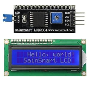
The backpack uses a PCF8574 i/o expander to drive the hd44780 pins.
It will require examining the actual LCD backpack PCB to figure out how the output port pins are wired up, specifically pins 4,5,6,7,9,10,11 and 12.
(this takes maybe 5 minutes, and may require an ohm meter)

And then reading the hd44780 spec to get a grasp on the how the control signals work, how commands and data are sent to the LCD, and then the initialization sequence needed. In this case how to reliably put the LCD into 4 bit mode.
Time for this may vary but if even if you are not very familiar with data-sheets an hour should be enough time to get a good grasp on how the part works and the signal pins.

To play at this level, then learning how to read datasheets and understanding how the hardware works is a must.

For this project, once how the PCF8574 is wired and hd44780 4 bit mode is understood, then there would be no need to look at an i2c LCD library as how the interface worked would be understood.
And then it would be obvious what to send over i2c to control the LCD, which would allow writing the low level s/w routines to send the bytes and then the higher level API functions that sit on top of that to send characters or commands to the LCD - which is what the i2c lcd libraries do.

But if I really need to know how the I2C bytes translates into lcd instructions I just hook up 7 of the 8 channels of my logic analizer on my lcd screen and see how it works. And after that has been done, than I would recommend to take a dive in those complicated librariers. This is 100x more easy than what you suggest.

One can learn more out of hardware exercises than from complicated libraries. It sure take way less time to use a logic analizer and write down your findings than to entirely comprehend 3-4 different libraries which might take god knows how many days if not weeks.

This is the wrong approach, particularly in this case where documentation is readily available. While hooking up probes and attempting to reverse engineer the interface can work for certain situations, it should be a mechanism of last resort since it does not really ever offer the ability to truly know and understand the interface.

And given your previous comments it seems that the even after this initial reverse engineering exercise, it is still not understood how to control the LCD for characters and commands.

Reverse engineering is also often much more time consuming than simply reading the documentation/specifications.
This methodology also cannot ever offer a complete picture of how the interface fully works, nor will it provide any information related to initialization or timing requirements/boundaries, all of which are in the hardware specifications.
Also, keep in mind that by looking at signals for a working system you are only examining what THAT particular system is doing.
It is a specific implementation that may or may not be following the specification and it may or may not be able to provide enough information to grasp the real full interface and its timing requirements.
That is why reverse engineering can be so difficult and often leads to less than optimum solutions.

In this case it is simply not needed, as you have direct access to the backpack to easily determine the design and its wiring and hd44780 specs are readily available for free from the internet.

Once the interfaces are understood, that knowledge could be used for other situations/projects.
It would directly transfer to know how to use a different i2c backpack that used the same PCF8574 but was wired differently, or even another interface like a shift register implementation.

--- bill

Gotta give him credit for enthusiasm though! :roll_eyes: