I2C LCD Doesn't write anything

hello everyone,

firstly I apologize for any mistakes in the text, english isn't my 1st language

I have to use a MC21605C6W-SPTLYI-V2 LCD with native I2C interface for a school project

However, despite all my tries it doesn't show any text at all on the LCD. I've been using chatpgt so far (i know, i know....) to try and debug my problems, but it has been unsuccessful so far.

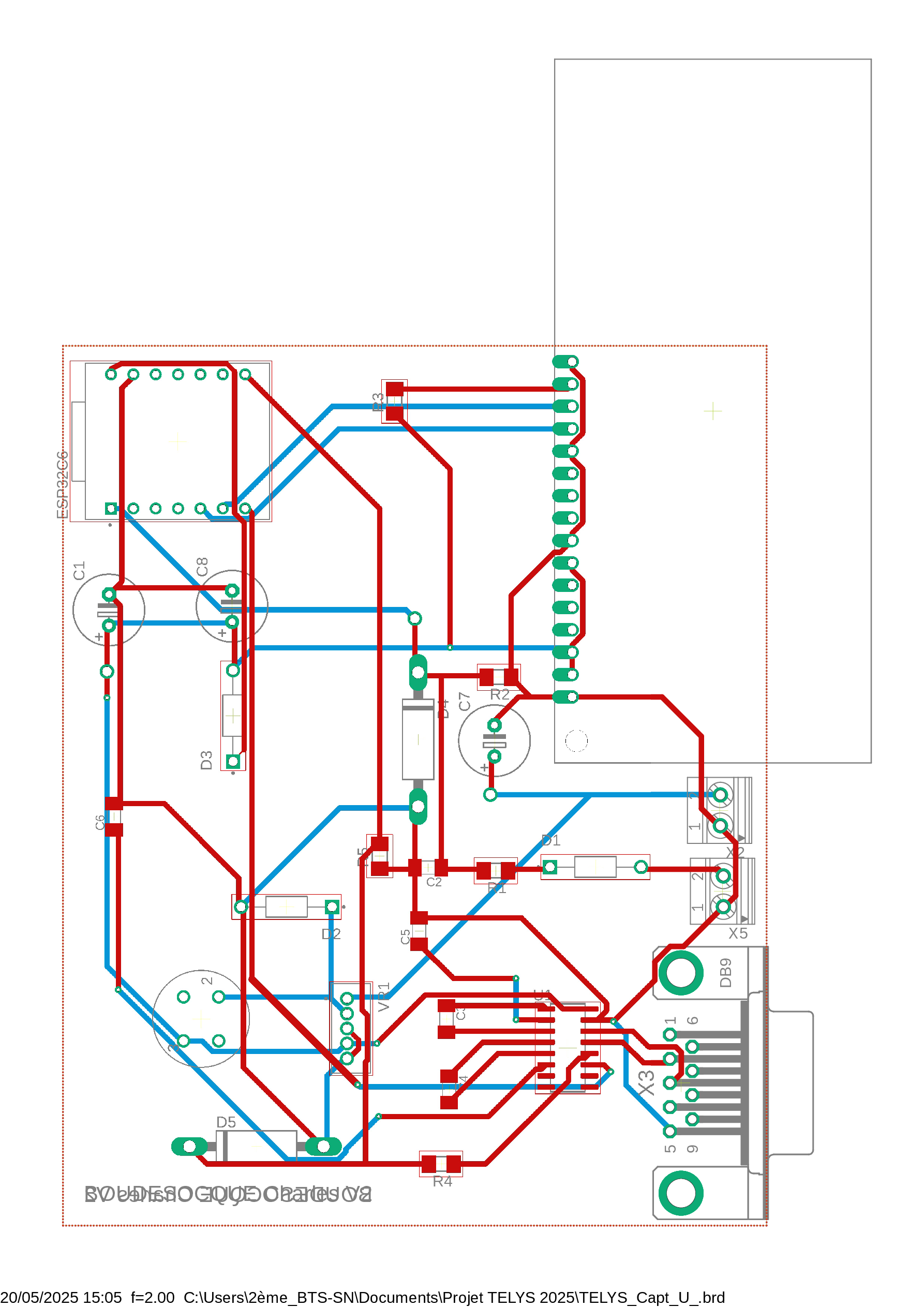
I am using a XIAO ESP32-C6 and the screen is powered externally with a generator. My schematic:

Every pin that needs voltage has 5V except the SCL and SDA pins that get 3.3V due to them coming out of the ESP32.

According to the MC21605C6W-SPTLYI-V2 datasheet (that you can find here), I would need pull-up resistors on SCL and SDA that I haven't put on, which would be frankly annoying since I would need to fabricate another PCB, and I don't really have the time to (project deadline is on the 10th of june)

I've tested if the LCD is connected using an I2C address scanner and i've found that it is connected at the 0x3D address.

I've tried using Adafruit_liquidcrystal library, the U8g2 library, the hd44780 library and the Wire library.

Here is my current code

#include <Wire.h>
#include <hd44780.h>
#include <hd44780ioClass/hd44780_I2Cexp.h>

hd44780_I2Cexp lcd;

void setup() {
  Serial.begin(115200);
  delay(500);

  // Initialise wire with the right GPIOs for the ESP
  Wire.begin(D4, D5); // SDA = GPIO6 (D4), SCL = GPIO7 (D5)

  Serial.println("Scan I2C en cours...");
  Wire.beginTransmission(0x3D);
  if (Wire.endTransmission() == 0) {
    Serial.println("LCD détecté à l'adresse 0x3D"); // lcd detected at the 0x3D address
  } else {
    Serial.println("Aucun LCD détecté à 0x3D !");// No LCD detected at the 0x3D address
    while (1);
  }

  // Initialize the display 
  int status = lcd.begin(16, 2); 
  if (status) {
    Serial.print("Erreur d'init LCD : code "); // if any error occurs, sends the error code
    Serial.println(status);
    while (1);
  }

  lcd.backlight();
  lcd.setCursor(0, 0);
  lcd.print("Hello XIAO C6!");
  lcd.setCursor(0, 1);
  lcd.print("I2C @ 0x3D");
}

void loop() {
  // empty
}

Thanks in advance for any help, don't hesitate to ask me for more details if needed.

I think you need to attach those pullup resistors somehow (maybe on the LCD?)
Not saying that is the issue, but you need to rule it out.
BTW, I always use the following library with no problems and NO pullups

I forgot to mention I also tried that library, to no avail...

I could try to add those pullup resistors but it isn't going to be pretty since i'd have to cut open some of the connections with a box cutter and solder a resistor on top, AND my Sda and SCL connections are on the underside of the PCB :smiling_face_with_tear: which is why I'm hoping to find some alternative to butchering it :joy: Here is my board schematic:

I think one of my main problems is that i can't seem to find a library that works with the controller of my LCD, which is a RW1063.

I am confused. The LCD's I am familiar with have a small board on the back of the display that convert the SPI connections to I2C. As a result onlyh 4 wires exit the LCD, G, VCC, SDA, and SCL. The library I mentioned is ONLY for this kind of I2C setup.
If you would post a photo of the front and back of the screen making sure the image fills the display so we can read the pins etc. then we might have more info.

If you go to this website https://midasdisplays.com/shop/lcd/lcd-character/mc21605c6w-sptlyi-v2/ you can get the datasheet of the LCD by clicking on 'specification' where you can see the pinout of the LCD, there's 16 pins but a bunch of them are unused. There are a lot since this LCD can work in I2C but doesn't always do (from what I understand) , there's a CS pin to toggle it on or off, there's also 2 pins for the backlight, 2 pins for the slave addresses,


Here's a photo of the LCD as well

That is NOT an I2C board, it's SPI. I think you can buy the backpack board but not sure. The backpack board has a lot of components so it's not a simple change. Here is a Amazon.CA link to just the backpack, but for an extra $1 you can get 4 backpacks and 4 1602 LCD's. Try the usual suspects for better pricing.
https://amz.cx/3SDl

I do already use SPI in another part of my project, which uses the RX/TX pins of my ESP, Also the constructor website and the datasheet both state that it is I2C, and there's no I am a bit confused ? An SPI LCD would have a MISO/MOSI pin set which are not present here

datasheet pic

Description on the MIDAS Displays page

Edit: added screenshots to support what i said

1 Like

Ok, it must be a totally different board, I have seen dozens and none like yours.
Solved in forum a while ago. Here is thread, see posts #2 and #5.
https://forum.arduino.cc/t/solved-midas-mc42005a6w-sptlyi-v2-hums-lcd-project/687386/4

Thank you for this,

My school day just ended so I Will check this out tomorrow and get back here with my results :thinking:

That LCD device appears to be configurable for parallel, SPI and I2C.
The jumpers IF0 and IF1 control the mode.
In your photo, it appears that the jumpers JIF0 and JIF1 are set for I2C mode.

From looking at the datasheet the I2C communications protocol is using the same as protocol as the PCF2116/PCF2119x or the AIP30168 chipsets.

The hd44780 library includes support for that LCD protocol over I2C.
You will want use the hd44780_I2Clcd i/o class.

It isn't clear if the CSB pin is used when in I2C mode. I'm guessing it is not used in I2C mode and is only used in SPI mode.

One issue you have is that the LCD is 5v but your processor is 3v.
To interface 3v and 5v logic a level shifter is normally used.
I highly recommend using a level shifter since Interfacing 3v logic signals to 5v logic signals can have issues.
Issues like damaging components or not being reliable depending on the specific signals.

Using a level shifter splits/separates/isolates the i2c signals into two sides.
A 5v side and a 3v side so that the SDA and SCL signals for the LCD device side can be pulled up to 5v and the SDA and SCL signals on the MCU side can be pulled up to 3v.

--- bill

A level shifter board also includes pull up resistors on both sides.
Leo..

True.
Also, some have a 5v to 3v regulator on them and some require supplying the voltage for each side.
For this application, a 5v to 3v regulator is not needed.
If using one with a 5v to 3v regulator you do not want to hook up the 3v power output on the level shifter to the 3v power output on the 3v MCU board.

--- bill

Hey guys !

Sorry for the late response, I was busy trying a bunch of stuff.

So, according to the RW1063 documentation, it DOES work with 3.3V

And i've found the source of my problems: The V0 pin.

That V0 pin was at 5V when it controls the contrast of the LCD. I had to isolate the pin by cutting the connections and soldering a cable on top of the LCD like a barbarian, but it works !

it needed around 0.7V to display text nicely.

Thank you for your help, it definitely hepled me pinpoint what was working and what wasn't