Esp32 c3 mini - 2004A I2C lcd connection problem

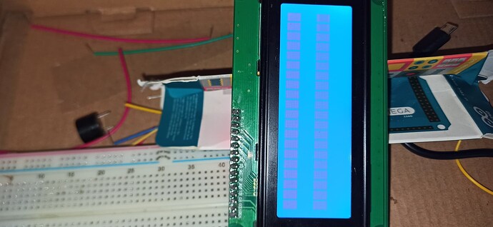
I have an ESP32-C3-DevKitM-1 board connected to an LCD 2004A using an I2C module. I'm using pin 8 for SDA and pin 9 for SCL. The thing is, in the Wokwi simulator, this circuit works perfectly fine, and the text appears on the screen. However, when I replicate it on the physical board, the LCD lights up but doesn't display any text.

Here's the simulation link:

I have tried both LCD models (16x2 and 20x4) by changing the values in "LiquidCrystal_I2C lcd(0x27, 20, 4);" to "LiquidCrystal_I2C lcd(0x27, 16, 2);".

I am also sending some pictures of the physical setup.


Can anyone tell me how to solve this? It's a very basic "Hello World" example, but I can't get it to work...

Thank you very much.

The blue device on the I2C adapter that is mounted on your display is a potentiometer that is used to derive the contrast voltage for the display.

That voltage can be set anywhere from 0 to Vcc or in the case of a circuit supplied by an ESP device anywhere between 0 and 3.3v above GND.

The display datasheet specifies the contrast voltage with respect to Vcc not GND, and it is typically 4 or 5 volts less than Vcc. Therefore, when using a 5 volt supply for Vcc, the contrast voltage will typically be between 0 and 1 volt with respect to GND.

When using a 3.3v supply for Vcc the contrast voltage would have to be -0.7 to -1.7 volts
which is out of range for the potentiometer in your case.

Some display modules contain a 'charge pump' that can generate the required negative voltage for the contrast pin. If yours were such a device then the pads just above the "2004A" marking on your board would be populated.

Don

Thank you very much for your response.
I'm not quite understanding what the solution is to my problem of why the LCD is not displaying the text.
I apologize for my ignorance, but I am new to programming Esp32.

Best regards.

The bottom line is that you need to use an LCD module that is designed to operate at 3.3v rather than the more common 5v devices.

Don

2 Likes

Run I2Cscanner to make sure your module has address 0x27.

Thank you very much for your response.

I used this code to scan the I2C address:

And the result was:
"I2C device found at address 0x3F."

So, I changed this line of code:
"LiquidCrystal_I2C lcd(0x3F, 20, 4);"

And now, I can see some text on the LCD, but with very little contrast (I believe the issue of the text not having much contrast is due to the voltage, as @floresta mentioned.), and it's not the text I'm sending to the LCD, but at least I can see something.

I'm not sure if the characters on the screen are distinguishable, but this is the result.

Now, my question is, why do these characters appear instead of the text I'm sending to the LCD?

That's because the wiring on your I2C adapter does not agree with the assumptions made by the perpetrator author of the I2C library that you are using.

You really should look into using the 'HD44780' library.

Don

2 Likes

For an I2C LCD display to work, the I2C address and the I2C backpack to LCD pin mapping must be correct. If the library default settings for either or both are not correct the LCD will not work. You can try to figure out the right pin mapping and use an I2C scanner to find the address, but if you install and use the hd44780 library (mentioned by @floresta) that is done automatically by the library.

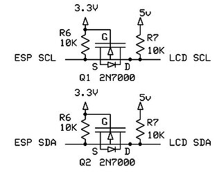
To use a 5V LCD with a 3.3V processor, power the LCD with 5V and use levels shifters on the I2C lines to shift the 5V LCD signals to 3.3V for the processor.

1 Like

Tweak the contrast pot on the I2C backpack.

@argomari
the soldering of the module doesn't look very clean.
this can lead to short circuits.
You could try to clean the board or try with another module.

1 Like

Thank you very much, I will try the "level shifter" and review the library you mentioned this week.

Best regards, and thank you very much for your help.

You can buy the level shifter ready made from, for instance, Amazon.

Level shifter

The hd44780 library is available via the IDE library manager.
The class that you want to use is the hd44780_I2Cexp class. There are examples to show how to use the library. The nice thing about the hd44780 library is that it will autodetect the I2C address and the I2C backpack to LCD pin mapping.

In the examples, there is a diagnostic sketch that will help us to help you if you still have trouble with the display. Run the diagnostic sketch and post the results.

Path to the hd44780 library "Hello World" example, diagnostic sketch and documentation.

1 Like

Thank you very much, everyone, for your help.
In the end, I managed to solve the problem by adding a "charBitmap" in the LiquidCrystal_I2C library, and the code now looks like this:

#include <Wire.h> // needed for LCD with PCF8574 port expander
#include <LiquidCrystal_I2C.h>
LiquidCrystal_I2C lcd(0x3F, 20, 4); // set the LCD address to 0x27 for a 16 chars and 2 line display

// Creat a set of new characters
const uint8_t charBitmap[][8] = {
    {0xc, 0x12, 0x12, 0xc, 0, 0, 0, 0},
    {0x6, 0x9, 0x9, 0x6, 0, 0, 0, 0},
    {0x0, 0x6, 0x9, 0x9, 0x6, 0, 0, 0x0},
    {0x0, 0xc, 0x12, 0x12, 0xc, 0, 0, 0x0},
    {0x0, 0x0, 0xc, 0x12, 0x12, 0xc, 0, 0x0},
    {0x0, 0x0, 0x6, 0x9, 0x9, 0x6, 0, 0x0},
    {0x0, 0x0, 0x0, 0x6, 0x9, 0x9, 0x6, 0x0},
    {0x0, 0x0, 0x0, 0xc, 0x12, 0x12, 0xc, 0x0}

};

void setup()
{
  int charBitmapSize = (sizeof(charBitmap) / sizeof(charBitmap[0]));
  Wire.begin(6, 7);
  for (int i = 0; i < charBitmapSize; i++)
  {
    lcd.createChar(i, (uint8_t *)charBitmap[i]);
  }

  lcd.init(); // initialize the lcd
  // Print a message to the LCD.
  lcd.backlight();
  lcd.setCursor(1, 0);
  lcd.print("Hello, world !");
  lcd.setCursor(2, 1);
  lcd.print("ESP32-C3 I2C");
}

void loop()
{
}

Anyway, I will try the hd44780 library to expand my knowledge with LCDs.
I just have to implement the "level shifter," and that will address all my concerns up to now.

Thanks again to all of you for your help and for providing links and additional information about the problem.

Best regards.

the point is - it makes absolutely no sense to create special characters before the lcd.init().

if the current sketch works, I assume you can replace your for loop with a simple delay(500), the LCD will get enough time to settle its internal controllers and will be ready to do its lcd.init() afterwards.

1 Like

You have not solved the problem but are merely masking it.
Whatever the real issue is will come back and bite you.

The reason calling lcd.createChar() before lcd.init() makes no sense is that until the sketch calls lcd.init() the Arduino board cannot communicate with the LCD as the i2c adapter needs the LCD to be in 4 bit mode and the LCD powers up in 8 bit mode.
Calling lcd.init() puts the LCD into 4 bit mode.

If there is some sort of startup timing issue, what you have done may appear to work.
However, it is doing some odd things that you may not realize.
The first time the code runs after a power up, lcd.createchar() will send garbage to the LCD but lcd.init() will initialize the LCD to 4 bit mode.
The 2nd time the code runs lcd.createchar() will work since the LCD is already in 4 bit mode. The lcd.init() on the 2nd run will simply re-initialzed the LCD back to a default state in 4 bit mode.

--- bill

1 Like

You're right, you're correct. Simply adding a delay(500) before executing lcd.init() is sufficient. The "for" loop is not really solving the problem.

Therefore, just by adding a delay(500) at the beginning of "setup," the characters are displayed correctly on the LCD.

Therefore, the code would look like this:

#include <Wire.h> // needed for LCD with PCF8574 port expander
#include <LiquidCrystal_I2C.h>
LiquidCrystal_I2C lcd(0x3F, 20, 4); // set the LCD address to 0x27 for a 16 chars and 2 line display

void setup()
{
  Wire.begin(6, 7);

  delay(500);
  
lcd.init(); // initialize the lcd
  // Print a message to the LCD.
  lcd.backlight();
  lcd.setCursor(1, 0);
  lcd.print("Hello, world !");
  lcd.setCursor(2, 1);
  lcd.print("ESP32-C3 I2C");
}

void loop()
{
}

Thank you very much for everything, and especially for the explanations, as I'm learning a lot from this post.

Best regards.

Today, I received the "level shifter," and I'm trying to connect it properly, but it doesn't work. I connected the ESP32 to the level shifter and then to the LCD, like this:

Is this the correct way to connect it?

This is the "Level Shifter":
https://www.amazon.es/dp/B095H64XSV?psc=1&ref=ppx_yo2ov_dt_b_product_details

if the schematic is right and you have connected the PCF & LCD to 3.3V ... why do you need a level shifter?

Until you really know what the issue is, you have no way of knowing that you have really solved the issue.

Your latest "solution" is enough to get you past this first issue, there may be more.

One way to get a better idea of what the issue might be is to hook up a logic analyzer and look at the signals going to the LCD and see if they conform to the signal timing in the datasheet for the specific LCD panels that you have.

I would suggest trying the hd44780 library.
Not only does it come with a diagnostic tool to help diagnose issues, but has been tested against many different LCDs and on many different Arduino h/w board platforms. In some cases it even has specific work arounds for certain h/w platforms due to timing or issues in s/w on those platforms.

--- bill

1 Like

I would say no but I can't really tell since the minimal schematic you posted does not accurately reflect that h/w that you have and, IMO/guess, is likely not how you have actually wired things up.

You have an ESP32 board hooked up to i2c backpack so we need to how you have actually wired up everything now that you have changed the wiring from what you posted earlier.

i.e. your schematic shows what voltage goes to the LCD but not what voltage is powering the backpack (PCF8574 i2c expander chip).

i2c backpacks like the one you are using have a VCC pin on the header.
That VCC pin runs power to the PCF8574 chip, the onboard pullups,
and powers the LCD.
In most cases, the LCD needs 5v to get proper contrast as most of the low cost LCDs are 5v parts.

If you need to run the LCD at 5v the easiest way to do that is run the backpack at 5v but that also means the i2c bus signals going to the backpack will be 5v.
And because the i2c backpack i2c signals are running at 5v and the esp32 runs its i2c signals at 3v, a level shifter is required to connect the 3v ESP32 i2c bus to work with the 5v i2c bus of the i2c backpack.

If you don't use a level shifter and directly connect the 3v ESP32 signals directly to a 5v i2c bus, you run the risk of frying the 3v ESP32 since you are connecting its 3v signals to 5v signals.

In terms of how to hook up a level shifter.
A level shifter can be used to connect two i2c busses of different voltages.
Typically this is used to connect a 3v bus to a 5v bus.

I have seen two types of low cost level shifters.

  1. onboard 3v regulator
  2. no onboard 3v regular

If you have type 1 level shifter, there is 5v pin and a 3v pin.
The 5v pin is an input that you connect to 5v and the level shifter creates the 3v on board using a regulator so the 3v signal is an output, not an input.
If connecting a 5v processor to a 3v devices, you can use the 3v pin to power your 3v devices.
If connecting a 3v processor to 5v devices, you leave the 3v pin disconnected.

If you have type 2 level shifter.
These have two voltage inputs. Often labeled as, LV/HV, A/B, L/H, or 1/2
Both voltage pins are inputs.
Connect one side to 5v for the 5v i2c signals, and connect the other side to 3v for the 3v signals.

From your link you appear to have type 2

--- bill