i2c multiplexing with TCA9548A from Adafruit

Hi,

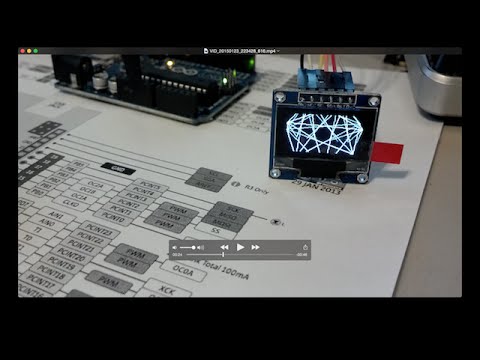
I'm wanting to run multiple SSD_1306 OLED displays using the Adafruit TCA9548A. The video below shows 4 screens running from an Arduino Due - seems to run the fastest of my boards.

Usually, the Teensy smashes everything else in terms of speed, but not in this case.

Is there any way to speed up the display re-draw? I'm expecting a new Teensy 3.6 shortly, but apart from getting the fastest board available, is there anything I'm doing in code that is slowing things down?

I realise I'm repeating a lot of calculation, but the code posted is the only way I can seem to get the system to work...

On a slightly different tack, bearing in mind I'd like to use many screens in an installation, I could use a PC or Mac to drive these things - but how? And would it make any difference, or is the bottleneck in the screen re-draw on the SSD 1306s?

Any advice would be gratefully received!

This code is very much mostly written by Hari Wiguna...

Thanks Harry!

/*********************************************************************
  This is an example for our Monochrome OLEDs based on SSD1306 drivers

  Pick one up today in the adafruit shop!
  ------> http://www.adafruit.com/  category/63_98

  This example is for a 128x64 size display using I2C to communicate
  3 pins are required to interface (2 I2C and one reset)

  Adafruit invests time and resources providing this open source code,
  please support Adafruit and open-source hardware by purchasing
  products from Adafruit!

  Written by Limor Fried/Ladyada  for Adafruit Industries.
  BSD license, check license.txt for more information
  All text above, and the splash screen must be included in any redistribution
*********************************************************************/

#include <Wire.h>
#include <Adafruit_GFX.h>
#include <Adafruit_SSD1306.h>

#define OLED_RESET 4
Adafruit_SSD1306 display(OLED_RESET);

#if (SSD1306_LCDHEIGHT != 64)
#error("Height incorrect, please fix Adafruit_SSD1306.h!");
#endif


int nFrames = 36;


#define TCAADDR 0x70

void tcaselect(uint8_t i) {
  if (i > 7) return;

  Wire.beginTransmission(TCAADDR);
  Wire.write(1 << i);
  Wire.endTransmission();
}


void setup() {
  Serial.begin(115200);

  // by default, we'll generate the high voltage from the 3.3v line internally! (neat!)
  display.begin(SSD1306_SWITCHCAPVCC, 0x3c);


  display.clearDisplay();
}

void loop() {

  for (int frame = 0; frame < nFrames; frame++)
  {
    HariChord(frame);
  }

  for (int frame = (nFrames - 1); frame >= 0; frame--)
  {
    HariChord(frame);
  }

}

void HariChord(int frame)
{

  display.clearDisplay();
  int n = 7;
  int r = frame * 128 / nFrames;
  float rot = frame * 2 * PI / nFrames;

tcaselect(3);
  for (int i = 0; i < (n - 1); i++)
  {

    float a = rot + i * 2 * PI / n;
    int x1 = 0 + cos(a) * r;
    int y1 = 0 + sin(a) * r;

    for (int j = i + 1; j < n; j++)
    {
      a = rot + j * 2 * PI / n;
      int x2 = 0 + cos(a) * r;
      int y2 = 0 + sin(a) * r;

      display.drawLine(x1, y1, x2, y2, WHITE);
    }
  }
  display.display();
  display.clearDisplay();

  tcaselect(2);
  for (int i = 0; i < (n - 1); i++)
  {

    float a = rot + i * 2 * PI / n;
    int x1 = 128 + cos(a) * r;
    int y1 = 0 + sin(a) * r;

    for (int j = i + 1; j < n; j++)
    {
      a = rot + j * 2 * PI / n;
      int x2 = 128 + cos(a) * r;
      int y2 = 0 + sin(a) * r;

      display.drawLine(x1, y1, x2, y2, WHITE);
    }
  }
  display.display();
  display.clearDisplay();

  
  tcaselect(1);
  for (int i = 0; i < (n - 1); i++)
  {

    float a = rot + i * 2 * PI / n;
    int x1 = 0 + cos(a) * r;
    int y1 = 64 + sin(a) * r;

    for (int j = i + 1; j < n; j++)
    {
      a = rot + j * 2 * PI / n;
      int x2 = 0 + cos(a) * r;
      int y2 = 64 + sin(a) * r;

      display.drawLine(x1, y1, x2, y2, WHITE);
    }
  }
  display.display();
  display.clearDisplay();

  tcaselect(0);
  for (int i = 0; i < (n - 1); i++)
  {

    float a = rot + i * 2 * PI / n;
    int x1 = 128 + cos(a) * r;
    int y1 = 64 + sin(a) * r;

    for (int j = i + 1; j < n; j++)
    {
      a = rot + j * 2 * PI / n;
      int x2 = 128 + cos(a) * r;
      int y2 = 64 + sin(a) * r;

      display.drawLine(x1, y1, x2, y2, WHITE);
    }
  }
  display.display();
  display.clearDisplay();

}

Many Thanks.
The bottleneck is the I2C, no matter how fast the possible goes the I2C only works at 100K bits per second. With other libraries you can get it to run faster but not very much faster. Speeds are 400K and 1.3M, although I have never managed to get anything going that fast, 800K is the fastest I have got but it depends on the device. Look at the I2CMaster library.

SPI is much faster than I2C (module does both), and the module has a CS (chip select) pin.
AFAIK no need for a muxer.
Leo..

Ah, I need to look into SPI - but AFAIK, there s no CS pin - just clk and data...?

The Adafruit module has a CS pin.
So the chip itself must have a CS line.
Probably not brought out to a pin.
Check the back of the module.
Leo..

I get so confused about this - which pin on the Arduino to which pin on the display, some pins are declared but not physically used, certain pins can and cannot be used! Halp!

Using u8gc, I can get the I2C version to run:

U8GLIB_SSD1306_128X64 u8g(U8G_I2C_OPT_DEV_0|U8G_I2C_OPT_NO_ACK|U8G_I2C_OPT_FAST);	// Fast I2C / TWI

My display is a very cheap one from ebay - it only has four pins... Can I use SPI with this?

Pins are: GND VCC SCL SDA..

Wonder why the first image is upside down?

The display itself (yellow ribbon) can be configurated for I2C or SPI. And it has a CS line (track 13?).
The parts on the blue carrier board force the display into I2C or SPI mode.
The boards you have bought has the display configurated for I2C, and has no jumpers to change to SPI.
And the CS ine is not available to the user.
If you are very skilled in smd, and adventurous, then look at the datasheet and Adafruit design files and start hacking.
Leo..

Ah, OK, thanks wawa!

I'm not skilled enough (but I am, maybe, just, adventurous enough!) to start hacking this little guy! But at least I know now that it's set for i2c only...

I bought a load of these, hoping to have an array that acted as a kind of 'video wall', with one image stretched across many display - as in the video I posted earlier on...

So you reckon I will not be able to increase the speed of the animation much?

I did notice a big difference when I plugged it into a Due, previously it was running on a Chinese nano... : )

So if want fast drawing, I'd have to shell out for a more expensive SPI ready display? any recommendations in the sam kind of form factor?

Thanks!

timothy_cubed:
So you reckon I will not be able to increase the speed of the animation much?

As Mike said earlier, you may be able to get them to work at 400KHz instead of the default 100KHz. Try putting "Wire.setClock(400000);" just after "Wire.begin();". If that works, and the speed increase is still not enough, then the next question you need the answer to is what's causing the slowness, updating the displays, or drawing the image? Do some timings in your code using the micros() function to find out.

If only a small part of the time is taken by updating the displays, then you need to look at making the rest of the sketch more efficient.

If it is the updating of the displays that is taking most of the time, then then you may need the SPI version of the display (which is what is shown in the youtube video you posted).

The Due is more suited to dealing with multiple displays, having more memory and a faster clock speed. You could look at other boards, such as Maple Mini, Teensy 3.x, ESP8266, all of which have similar capability to Due, are cheaper, smaller and and be used with the Arduino IDE and sketches.

timothy_cubed:
So if want fast drawing, I'd have to shell out for a more expensive SPI ready display? any recommendations in the sam kind of form factor?

I don't think the SPI version is much more expensive than the i2c version. They look identical, except the SPI version has 6 pins rather than 4. Shop around, butg be careful. Many sellers do not understand the terms SPI, i2c and serial and will confuse them. Make sure the displays you buy have 6 pins including a CS pin.

Paul, thanks - that's excellent. I made a bit of a beginners error, then, in buying the 4pin displays.

Will try running the i2c at 400KHz as you suggest and see what happens. Thanks again!

This one has 6 pins - is this OK for SPI? What does each pin acronym mean -0 and which pins do i attach on the Arduino?

It sells for £3.85 with free shipping, which is good I think...

http://www.ebay.co.uk/itm/White-0-96-SPI-SSD1306-128X64-OLED-LCD-Display-Module-Arduino-STM32-AVR-51-/181954941500?hash=item2a5d5c123c:g:rpwAAOSwp5JWZjfX

This is £2.55. Pins are different though...

http://www.ebay.co.uk/itm/0-96-I2C-IIC-SPI-Serial-128X64-OLED-LCD-Display-SSD1306-for-51-STM32-Arduino-/302104546088?var=&hash=item4656d58b28:m:muJX_cZd9CzUBJQEgcGlJPg

What are your thoughts?

Hmmm not sure about those. Neither has a chip select pin, which will be important if you are hooking up multiple displays.

EDIT: I do beg your pardon! The displays with a CS pin all seem to have 7 pins, not 6, including the one I have.

Ah, tricky! I wondered what the pins meant - what is D/C, and the D0, D1 pins, do you think?

Here's another... more expensive at £5.88:

http://www.ebay.co.uk/itm/Serial-128x64-OLED-LED-Display-Module-Screen-I2C-SPI-Blue-White-LCD-Arduino-/111474769297?var=&hash=item19f469fd91:m:mS5b9MAB6oxweEpRLC3AzCg

Another one with a C/S pin, at £4.88...

http://www.ebay.co.uk/itm/White-0-96-inch-SPI-Serial-Port-128-64-OLED-LCD-LCM-Display-Module-for-Arduino-/311550824326?hash=item4889e04f86:g:g-QAAOSw5VFWL0Gp

Wow - this is £2.77, but I'm worried about the silkscreen on the back - see photo. Does it mean I have to add / solder resistors to change the method (i2c / SPI) ?

http://www.ebay.co.uk/itm/White-3-5V-0-96-SPI-Serial-128X64-OLED-LCD-LED-Display-Module-for-Arduino-M0/152233990446?_trksid=p2054502.c100227.m3827&_trkparms=aid%3D111001%26algo%3DREC.SEED%26ao%3D1%26asc%3D20160908103841%26meid%3D8e277054392c4fed8f85ee9270aa28b3%26pid%3D100227%26rk%3D2%26rkt%3D15%26sd%3D131974541055

It's hard to say, looking at that picture.

Here is the back of mine. It is set for SPI.

The D0 & D1 are either MOSI and CLK for SPI mode or SDA & SCL for i2c mode.

D/C is Data/Command mode and is used only with SPI.

I have never used RST except to connect it to Vcc, so maybe that 6 pin you found would be OK.