I'm trying to use 5 Thermistor temperature sensors with an i2c 20x OLED character display on Arduino Uno r3. Currently, only 4 resistor analog inputs work because adding a 5th cancels out the oled display. Is it possible to use some of the digital pins to display onto the OLED, thereby freeing up extra analog input? If yes, how can I accomplish this?
In the Arduino IDE, in the menu is the "Library Manager". You can use it to install the SoftwareWire library. That library is not fully tested yet. Those OLED display are sometimes not fully compatible with I2C, I don't know what that will do with the SoftwareWire library. But since only data is written to the display and not read, I think it will work.
Could the USB 5v supply be the reason since it is limited in its current supply. Maybe adding a 5th analog pin causes the LED to drop out? Is the drop out limited to just Analog pin 5, or if you remove any one of the 5 analog pins the LCD will come back on?
chibullsan:
Could the USB 5v supply be the reason since it is limited in its current supply. Maybe adding a 5th analog pin causes the LED to drop out? Is the drop out limited to just Analog pin 5, or if you remove any one of the 5 analog pins the LCD will come back on?
No, it's nothing to do with that. It's because A4 and A5 are also the I2C pins. They can be used either as analogue inputs or as I2C communication pins, but not both at once.
The Arduino Leonardo has 12 analog inputs and is the same size as the Uno.
The Arduino Mega 2560 has 16 analog inputs, but it is bigger in size.
For 12 dollars you get a clone with very cheap components. It is not legal to call that an "Arduino". It may be called "Arduino compatible". They are less than 8 dollars on Ebay.
It's up to you. There are many boards and compatibles, maybe about 20 different flavours you can choose from.
The Uno is good to start with, but it has only 6 analog inputs, and two of them are also the I2C bus.
I picked up an Arduino Mega 2560 for $9 on sale :). [it was cheaper than the leonardo and pro mini] However, I'm learning Arduino sketch too slow. How would you guys suggest I display computer fan rpm (pwm) speeds and a thermistor temperature sensor values (converted to voltage divider with 10k ohm resistor and 5v output of Arduino) onto this OLED display with the following code sketch?
//***************************************//
// --- WIDE.HK---//
// --- Revised Date : 02/05/2014
// --- I2C Arduino - Arduino UNO Demo ---//
// --- SSD131x PMOLED Controller      ---//
// --- SCL, SDA, GND, VCC(3.3v -5v)   ---//
//***************************************//

#include <Wire.h>          // *** I2C Mode
#define OLED_Address 0x3c
#define OLED_Command_Mode 0x80
#define OLED_Data_Mode 0x40

void setup()
{
  Wire.begin();
}

void loop()
{
int i;
// *** I2C initial *** //
delay(100);
sendCommand(0x80);
sendCommand(0x2A); // **** Set "RE"=1 00101010B
sendCommand(0x71);
sendCommand(0xC0);
sendCommand(0x00);
sendCommand(0x28);

sendCommand(0x08); // **** Set Sleep Mode On
sendCommand(0x2A); // **** Set "RE"=1 00101010B
sendCommand(0x79); // **** Set "SD"=1 01111001B

sendCommand(0xD5);
sendCommand(0x70);
sendCommand(0x78); // **** Set "SD"=0

//sendCommand(0x08);
sendCommand(0x09); // **** Set 5-dot, 3 or 4 line(0x09), 1 or 2 line(0x08)


sendCommand(0x06); // **** Set Com31-->Com0  Seg0-->Seg99
sendCommand(0x72);
  sendCommand(0xC0);
   sendCommand(0x01);
// **** Set OLED Characterization *** //
sendCommand(0x2A);   // **** Set "RE"=1
sendCommand(0x79);   // **** Set "SD"=1

// **** CGROM/CGRAM Management *** //
// sendCommand(0x72);   // **** Set ROM
// sendCommand(0x00);   // **** Set ROM A and 8 CGRAM

sendCommand(0xDC);   // **** Set ROM
sendCommand(0x00);   // **** Set ROM A and 8 CGRAM

sendCommand(0xDA); // **** Set Seg Pins HW Config
sendCommand(0x10);

sendCommand(0x81);   // **** Set Contrast
sendCommand(0xD9);   //
  sendCommand(0x8F);   // **** Set Contrast

sendCommand(0xF1);

sendCommand(0xDB);   // **** Set VCOM deselect level
sendCommand(0x30);   // **** VCC x 0.83

sendCommand(0xDC);   // **** Set gpio - turn EN for 15V generator on.
sendCommand(0x03);

sendCommand(0x78);   // **** Exiting Set OLED Characterization
sendCommand(0x28);
//sendCommand(0x2A);
//sendCommand(0x05); // **** Set Entry Mode (invert)
sendCommand(0x06); // **** Set Entry Mode

sendCommand(0x28); // **** Set "IS"=0 , "RE" =0 //28
sendCommand(0x01);
sendCommand(0x80); // **** Set DDRAM Address to 0x80 (line 1 start)

delay(100);
sendCommand(0x0C);   // **** Turn on Display


// ********************************************************************//
// **** Show Data Value *** //

send_string("\0"); send_string("Rad Temp C   Fan RPM");   //1 ??line
send_string("\0"); send_string("R1 i:55 o:51  F=1100");   //2 ??line
send_string("\0"); send_string("R2 i:51 o:49  F=1200");   //3 ??line
send_string("\0"); send_string("R3 i:50 o:49  F=1200");   //4 ??line

/*
sendCommand(0x2C); //2 in 1 line

*/

while(1);

// **** Show Data Value *** //

}


void sendData(unsigned char data)
{
    Wire.beginTransmission(OLED_Address);   // **** Start I2C
    Wire.write(OLED_Data_Mode);     // **** Set OLED Data mode
    Wire.write(data);
    Wire.endTransmission();                     // **** End I2C
}

void sendCommand(unsigned char command)
{
    Wire.beginTransmission(OLED_Address); // **** Start I2C
    Wire.write(OLED_Command_Mode);     // **** Set OLED Command mode
    Wire.write(command);
    Wire.endTransmission();                 // **** End I2C
      delay(10);
}

void send_string(const char *String)
{
    unsigned char i=0;
    while(String[i])
    {
        sendData(String[i]);      // *** Show String to OLED
        i++;
    }
}
It is better to make everything work step by step. You could start to get the thermistor working without the display. Write the value to the serial monitor. Test for example if it can do negative temperatures as well.
This is a tutorial : Overview | Thermistor | Adafruit Learning System
Now, the thermistor setup is working and outputting values to the Serial monitor of Arduino software. Since I'm a total beginner and Koepel recommended to start simple, I started as simple as I could comprehend with the following code :):
This code sketch shows higher 3 digit numbers for hotter temperatures and lower 3 digit numbers for colder temperature in Arduino Serial Monitor.
Before I uploaded this new code-sketch to arduino, I left the OLED display plugged in and the new code sketch had no effect on the OLED display. So, although the thermistor sensor is working and outputting correct values to Arduino Serial Monitor software window, the oled display is also displaying the same as before with the old sketch :o . At least the oled display now works with all 5 analog inputs being used with i2c connections .
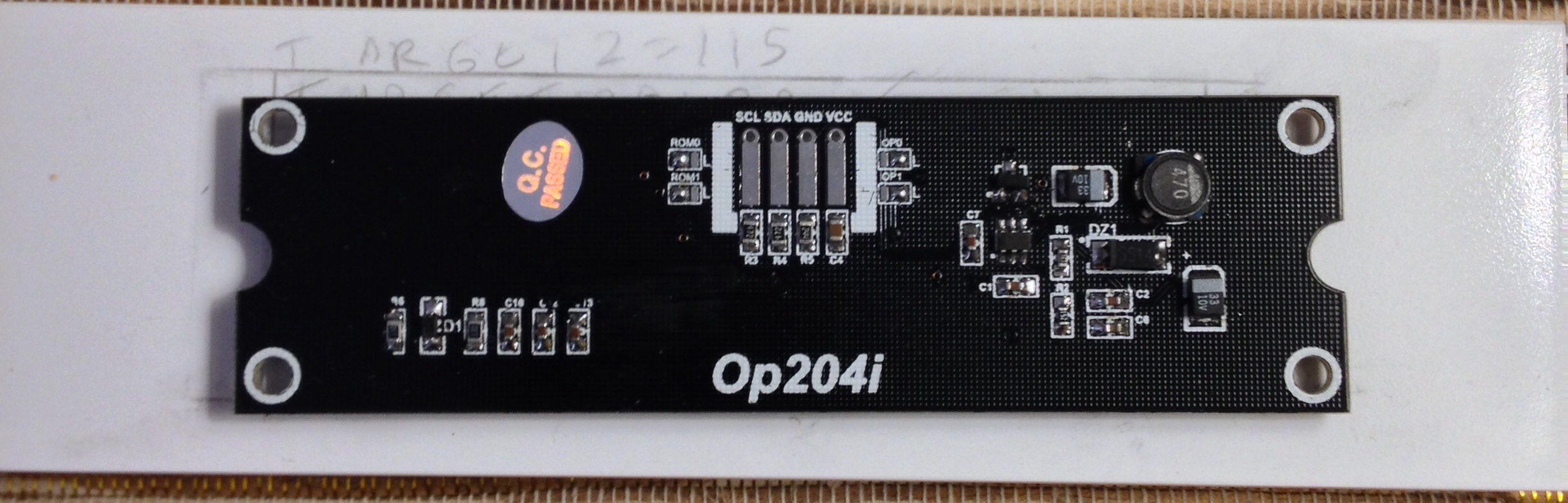
Any recommendations on how I can output this simple thermistor value onto the OLED display? The attachment shows back side of the 20x4 character oled display. op204i is printed on the back.
Why didn't you use the Adafruit tutorial that I mentioned ? That code shows the temperature instead of the raw analogRead() value.
The manufacturer of the OLED would be wide.hk ?
The type is Op204i, but I can't find that at wide.hk.
It seems to be a 20x4 character OLED display, because they have a Op162i which is 16x2 characters. The Op162i has a SSD1311 controller, perhaps the 20x4 has the same controller ?
The SSD1311 is a character controller for a 100x32 pixels OLED display. It has I2C, SPI, and an other interface. The I2C seems to only capable of writing data.
None of the SSD131x series is not supported by U8Glib.
The SSD131x series contains of the SSD1311 and SSD1316.
According to this : 16x2 OLED SSD1311 - Displays - Arduino Forum Adafruit has a display with SSD1311 controller. But I can't find Adafruit code for that controller with I2C mode.
They do have I2C code for the SSD1306. What are the differences between SSD1306 and SSD1316 ? I don't know.
Here, the Adafruit SSD1306 code is used on a SSD1316 without problem : OLED SSD1316 I2C con Arduino UNO
Perhaps that will work for a SSD1311 as well.
Another one is here : Making a custom 3D printer controller
This one is for 20x4. You will find a zip file with all the code. The OLedI2C.cpp and OLedI2C.h are in there and are a modified version of the 'gadjet' code.
Thank you for your info-sharing post. I followed your recommended Adafruit tutorial and got the thermistor outputting in Arduino serial monitor although it wasn't perfectly matching actual temperatures. When I tried to understand the Math of it all (in hopes of calibrating the thermistor for better accuracy), my eyes glazed over and I went into full adhd mode :o . But, at least thermistor setup works!
I tried to understand Flashgamer's OLED tutorial, but I'm totally lost on how to output this data onto the OLED display. Is there a more "noob" friendly tutorial you experienced Arduino'ers recommend that shows how to do this step-by-step?
Yes and it all outputs into Arduino Serial Monitor just like the ADafruit Sketch tutorial in your link. However, it seemed like the Thermistor's resistance to temperature relationship is not linear as temperatures get farther away from 25 Degrees Celsius in either direction (hot or cold).
Koepel:
Perhaps the BCOEFFICIENT of your ntc is a little different.
Perhaps your SERIESRESISTOR is not exactly 10k.
I altered BCoefficient's value and it would help within 1-2 degrees Celsius (at tested temperature), but after that temperatures were not within 1 degree precision. It's possible the 10K Thermistor is not exactly 10k and I need to tweak both BCoefficient and SeriesResitor values. If this doesn't improve accuracy enough, I can setup a temperature controlled bath and record each resistance at different temperatures, thereby creating an accurate temperature lookup table.
The Good = the thermistor is recording the temperature change (delta) decently enough to show changes in temperature.
To keep it simple as you recommended, the next step is How can I display what is currently being shown in Arduino Serial Monitor onto this OLED display? (Currently I'm re-reading the tutorial and hoping something clicks in my brain to make this all work together.) :-X
That is why most Arduino users start with an analog temperature sensor, and soon move over to the DS18B20. No more trouble with anything analog, it returns an accurate temperature via a digital 1-Wire interface.
I have read the posts in this topic again, and we didn't mention the DS18B20 before. Sorry for that. You only need one digital pin for 5 DS18B20 temperature sensors.
Marlin Oled sketch code used to display the above image:
/* -*- c++ -*- */

/*
    Reprap firmware based on Sprinter and grbl.
 Copyright (C) 2011 Camiel Gubbels / Erik van der Zalm

 This program is free software: you can redistribute it and/or modify
 it under the terms of the GNU General Public License as published by
 the Free Software Foundation, either version 3 of the License, or
 (at your option) any later version.

 This program is distributed in the hope that it will be useful,
 but WITHOUT ANY WARRANTY; without even the implied warranty of
 MERCHANTABILITY or FITNESS FOR A PARTICULAR PURPOSE.  See the
 GNU General Public License for more details.

 You should have received a copy of the GNU General Public License
 along with this program.  If not, see <http://www.gnu.org/licenses/>.
 */

/*
 This firmware is a mashup between Sprinter and grbl.
  (https://github.com/kliment/Sprinter)
  (https://github.com/simen/grbl/tree)

 It has preliminary support for Matthew Roberts advance algorithm
    http://reprap.org/pipermail/reprap-dev/2011-May/003323.html
 */

/* All the implementation is done in *.cpp files to get better compatibility with avr-gcc without the Arduino IDE */
/* Use this file to help the Arduino IDE find which Arduino libraries are needed and to keep documentation on GCode */

#include "Configuration.h"
#include "pins.h"

#ifdef ULTRA_LCD
  #if defined(LCD_I2C_TYPE_PCF8575)
    #include <Wire.h>
    #include <LiquidCrystal_I2C.h>
  #elif defined(LCD_I2C_TYPE_MCP23017) || defined(LCD_I2C_TYPE_MCP23008)
    #include <Wire.h>
    #include <LiquidTWI2.h>
  #elif defined(DOGLCD)
    #include <U8glib.h> // library for graphics LCD by Oli Kraus (https://code.google.com/p/u8glib/)
  #else
    #include <LiquidCrystal.h> // library for character LCD
  #endif
#endif

#if defined(DIGIPOTSS_PIN) && DIGIPOTSS_PIN > -1
#include <SPI.h>
#endif

#if defined(DIGIPOT_I2C)
  #include <Wire.h>
#endif
How do you guys recommend using MarlinOled library to display the Adafruit sketch's "Serial.print("Temperature ");" command onto the oled display? Here is the adafruit Thermistor sketch code I'm currently using that is working with Arduino software's 'Serial Montior':
// Which analog pin to connect
#define THERMISTORPIN A0

//resistance at 25 degrees C
#define THERMISTORNOMINAL 10000

// temp. for nominal resistance (almost always 25 C)
#define TEMPERATURENOMINAL 25

// how many samples to take and average, more takes longer
// but is more 'smooth'
#define NUMSAMPLES 5

//the beta coefficient of the thermistor (usally 3000-4000)
#define BCOEFFICIENT 3950

// the value of the 'other' resistor
#define SERIESRESISTOR 10000

int samples[NUMSAMPLES];

void setup(void) {
  Serial.begin(9600);
  // connect AREF to 3.3V and use that as VCC, less noisy!
  analogReference(EXTERNAL);
}

void loop(void) {
  uint8_t i;
  float average;

  // take N samples in a row, with a slight delay
  for (i=0; i< NUMSAMPLES; i++) {
    samples[i] = analogRead(THERMISTORPIN);
    delay(10);
  }

  // average all the samples out
  average = 0;
  for (i=0; i< NUMSAMPLES; i++) {
    average += samples[i];
  }
  average /= NUMSAMPLES;

  Serial.print("Average analog reading ");
  Serial.println(average);

  // convert the value to resistance
  average = 1023 / average - 1;
  average = SERIESRESISTOR / average;
  Serial.print("Thermistor resistance ");
  Serial.println(average);

float steinhart;
steinhart = average / THERMISTORNOMINAL;  // (R/Ro)
steinhart = log(steinhart);               // ln(R/Ro)
steinhart /= BCOEFFICIENT;                // 1/B * ln(R/Ro)
steinhart += 1.0 / (TEMPERATURENOMINAL + 273.15); // + (1/To)
steinhart = 1.0 / steinhart;              // Invert
steinhart -= 273.15;                      // convert to C

Serial.print("Temperature ");
Serial.print (steinhart);
Serial.println(" *C");

  delay(1000);
}